
A Radio Frequency transceiver library: nRF24L01 and ChibiOS/RT
Cheapest and most popular RF transceiver than ever
The nRF24L01 is one of the most popular RF transceiver as it is very cheap and it could be found already configured on small PCBs with needed passive components. This means that only a MCU is needed to design a radio system with the nRF24L01.
Description
The nRF24L01 is a highly integrated, ultra low power 2Mbps RF transceiver IC for the 2.4GHz ISM band. It provides an hardware protocol accelerator, the Enhanced ShockBurst, enabling the implementation of advanced and robust wireless connectivity with low cost MCUs.
Documentation
By this article we want to provide a full library for nRF24L01 compatible with ChibiOS/RT 3.0 ad a demo. That requires, as always, a preliminary read of the device datasheet.
Features
Design and connections
With peak RX/TX currents lower than 14mA, a sub μA power down mode, advanced power management, and a 1.9 to 3.6V supply range, the nRF24L01 provides a true ULP solution enabling months to years of battery lifetime when running on coin cells or AA/AAA batteries. The nRF24L01 is configured and operated through the SPI and using this interface we can access to its register maps contains all configuration registers of this chip.
Still using SPI we can send command to the transceiver making it accessible in all its operation modes.The Enhanced ShockBurst is based on packet communication and supports various modes from manual operation to advanced autonomous protocol operation. Internal FIFOs ensure a smooth data flow between the radio front end and the system’s MCU. The radio front end uses GFSK modulation and has user configurable parameters like frequency channel, output power and air data rate.
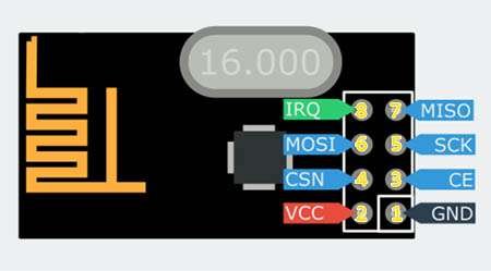
Pin Description
Just few pin are required to use this transceiver:2 pin for power supply, 4 pin for SPI communication and 2 additional pins for IRQ and CE. Follows the detailed pin map:
- GND, connection to ground
- VCC, power supply 1.9~3.6V DC
- CE, Chip enable used to perform some operation
- CSN, SPI chip select
- SCK, SPI serial clock
- MOSI, SPI MOSI
- MISO, SPI MISO
- IRQ, interrupt request pin
Enhanced ShockBurst
Enhanced ShockBurst is a packet based data link layer. It features automatic packet assembly and timing, automatic acknowledgement and re-transmissions of packets. It enables the implementation of ultra low power, high performance communication with low cost host MCUs. The features enable significant improvements of power efficiency for bi-directional and uni-directional systems, without adding complexity on the host controller side. This data link layer is enough complex and a reader can found a whole chapter (Chapter 7) about this argument on nRF24L01 reference manual.
Anyway, from our point of view we just need to know few thinks:
- We can set-up Enhanced ShockBurst using some commands clocked thought the SPI;
- Every receiver and transmitter need for a unique address which lenght is 5 bytes;
- Enhanced ShockBurst allows multiceiving (receive from 6 different addresses simultaneously);
- Max payload lenght is 32 bytes;
- Receiver is able to auto-detect payload lenght;
In this first library version we will not consider the multiceiver option: this requires just some additional APIs, but testing and debuging part would be much more difficult.
SPI Operation mode
Reading the reference manual (Chapter 8) we can understand that nRF24L01 uses a standard SPI with a maximum data rate of 8 Mbps. The serial commands are shifted out in this way: for each command word(one byte) most significant bit must be sent first; if the command is longer than one word less significant byte must be sent first. Chip select must be lowered before start communication and should be pulled up only when every word is shifted out.
A SPI timing diagram (see Fig.2) found on manual give us all the still missing information to configure SPI properly (If you are not expert about uses of SPI, we suggest our quick tutorial Meeting SPI).
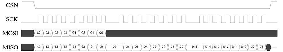
Summarizing, we need to configure SPI clock frequency to be equal or less of 8 MHz, Data size should be 8 bit, CPOL as low and CPHA as low.
We can found in the same chapter a table containing all the commands available (Figure 3), note that every SPI exchange length depends on commands and that we can access to every feature thought that commands. Furthermore during the first exchange nRF24L01 shift out the status register map.
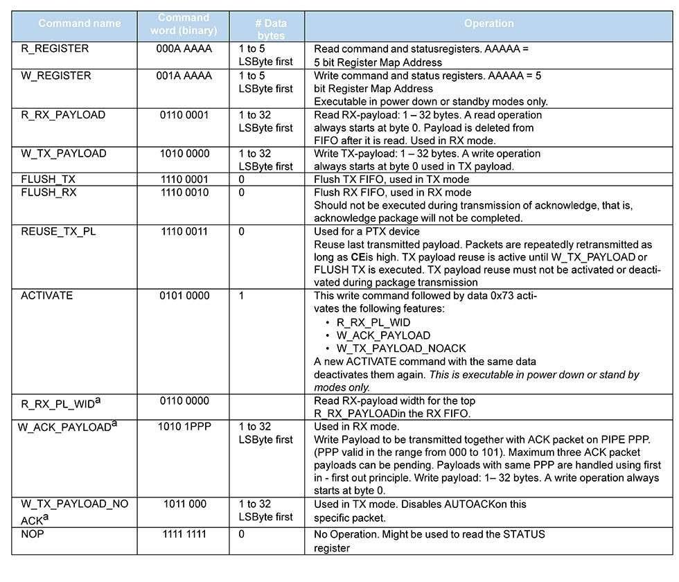
Equally important is the register map table (Chapter 9) We don’t report it here since it is very long, anyway remember that some configuration could be set-up writing in some of these registers.
The interrupt request
The nRF24L01 has an active low IRQ pin. The IRQ pin has three sources: it is activated when TX_DS (Transmit Data Sent), RX_DR (Receive Data Ready) or MAX_RT (Max Retransmit) bit are set high by the Enhanced ShockBurst in the STATUS register. The IRQ pin resets when MCU writes ‘1’ in the STATUS register on the bit associated to the IRQ active source. As example, we can suppose that a MAX_RT events happens. So, we will detect an IRQ transition from high to low and checking STATUS register we will found that MAX_RT bit is high. So we should take necessary actions and than set MAX_RT to high in the STATUS register to clear IRQ.
To detect IRQ we can use EXT driver from ChibiOS/HAL. This driver launches a callback when detects a transition (on rising, falling or both edge according to its configuration), anyway, we will discuss this callback in detail later.
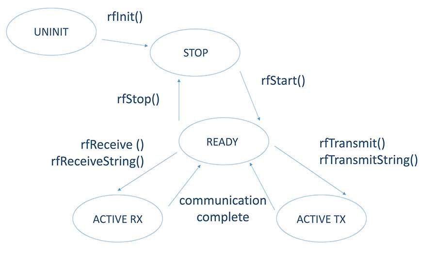
From finite state machine to driver design
Before starting, please allow me a little note. Not everyone knows that PLAY Embedded takes its name by an open-source library that we create some time ago. That library (a Pretty LAYer for ChibiOS aka PLAY for ChibiOS) is born to be an abstraction layer for most used devices in embedded applications and it already supports nRF24L01. The project is still active on sourceforge (PLAY) but from next versions it will support MEMS only. All this to say that code and ideas here presented are originating from that project.
Resuming, on chapter 6.1 we can found a finite state machine representing the modes the nRF24L01 can operate in and how they are accessed. Inspired by this diagram we made our driver FSM here represented (See Fig.4).
This is a good starting point for our driver design. About details on library organization we are confident that our loyal readers have already read articles like ChibiOS/HAL design and C Library design for embedded applications. Like for other libraries, this one has just a configuration header for user configuration or to disable driver, a main header rf.h and rf.c.
rf.h: typedefs and enumerations
As always, header contains a certain number of bit-mask and enumeration. We will just show important parts. First of all, we defined an RX packet and a TX packet. Note that Payload data structure is included into the frame and its length is fixed removing additional complications. The assumption considered during the design phase is that in the case of a communication using multiple packets it is expected that these have the same length. Anyway, payload length could be chosen thought userconf.h.
/**
 * @brief   RF transmission frame.
 */
typedef struct {
  /**
   * @brief   Address of the receiver.
   */
  uint8_t tx_address[RF_ADDLEN];
  /**
   * @brief   Static TX payload lenght.
   */
  uint8_t tx_paylen;
  /**
   * @brief   TX payload data structure.
   */
  uint8_t tx_payload[RF_PAYLEN];
} RFTxFrame;
/**
 * @brief   RF received frame.
 */
typedef struct {
  /**
   * @brief   Address of the transmitter.
   */
  uint8_t rx_address[RF_ADDLEN];
  /**
   * @brief   Static RX payload lenght.
   *
   * @detail  It is rewritten during a receive if Dynamic Payload Lenght
   *          feature is available.
   */
  uint8_t rx_paylen;
  /**
   * @brief   RX payload data structure.
   */
  uint8_t rx_payload[RF_PAYLEN];
} RFRxFrame;
Staring from enumeration and defines we can create a configuration structure. Additionally we need for CE and IRQ information, a pointer to an SPI driver and its configuration and a pointer to the an EXT driver and its configuration. We need for SPI for communication and for EXT to manage external IRQ.
/**
 * @brief   RF Transceiver configuration structure.
 */
typedef struct {
  /**
   * @brief The chip enable line port.
   */
  ioportid_t                ceport;
  /**
   * @brief The chip enable line pad number.
   */
  uint16_t                  cepad;
  /**
   * @brief The interrupt line port.
   */
  ioportid_t                irqport;
  /**
   * @brief The interrupt line pad number.
   */
  uint16_t                  irqpad;
  /**
   * @brief Pointer to the SPI driver associated to this RF.
   */
  SPIDriver                 *spip;
  /**
   * @brief Pointer to the SPI configuration .
   */
  const SPIConfig           *spicfg;
  /**
   * @brief Pointer to the SPI driver associated to this RF.
   */
  EXTDriver                 *extp;
  /**
   * @brief Pointer to the SPI configuration .
   */
  const EXTConfig           *extcfg;
  /**
   * @brief RF Transceiver auto retransmit count.
   */
  NRF24L01_ARC_t            auto_retr_count;
  /**
   * @brief RF Transceiver auto retransmit delay.
   */
  NRF24L01_ARD_t            auto_retr_delay;
  /**
   * @brief RF Transceiver address width.
   */
  NRF24L01_AW_t             address_width;
  /**
   * @brief RF Transceiver channel frequency.
   */
  NRF24L01_RF_CH_t          channel_freq;
  /**
   * @brief RF Transceiver air data rate.
   */
  NRF24L01_ADR_t            data_rate;
  /**
   * @brief RF Transceiver output power.
   */
  NRF24L01_PWR_t            out_pwr;
  /**
   * @brief   RF Transceiver Low Noise Amplifier
   */
  NRF24L01_LNA_t            lna;
  /**
  * @brief    RF Transceiver Dynamic Payload enabler
  */
  NRF24L01_DPL_t            en_dpl;
  /**
   * @brief   RF Transceiver Dynamic Acknowledge with Payload enabler
   */
  NRF24L01_ACK_PAY_t        en_ack_pay;
  /**
   * @brief   RF Transceiver Dynamic Acknowledge enabler
   */
  NRF24L01_DYN_ACK_t        en_dyn_ack;
} RFConfig;
According to our diagram these are RF available states:
/**
 * @brief   Driver state machine possible states.
 */
typedef enum {
  RF_UNINIT = 0,                     /**< Not initialized.                   */
  RF_STOP = 1,                       /**< Stopped.                           */
  RF_READY = 2,                      /**< Ready for TX or RX.                */
  RF_RX = 3,                         /**< Receiving data.                    */
  RF_TX = 4                          /**< Sending data.                      */
} rf_state_t;
Before to introduce RF driver typedef let’s spend some words about callback that occurs on IRQ. This callback could be considered like an ISR and in Real Time systems these routines should be atomic and their lifetime should be deterministic. We said above that IRQ has many sources and that we need to read STATUS register to understand the source that generated the IRQ. The lifetime of an SPI operation is by its very nature non-deterministic and as a general rule a driver should not be used in ISR.
We can solve this problem using another kernel instruments: events! The ISR broadcast an event, in this way we can manage STATUS register out of kernel critical section. That explains why in driver typedef we have some variable related to events: we have an event sources and an event listener.
/**
 * @brief   Structure representing a RF driver.
 */
typedef struct {
  /**
   * @brief Driver state.
   */
  rf_state_t         state;
  /**
   * @brief Current configuration data.
   */
  RFConfig           *config;
  /**
   * @brief   IRQ event.
   * @note    The flags associated to the listeners will indicate the
   *          IRQ mask that have occurred.
   */
  event_source_t      irq_event;
  /**
   * @brief   RF event listner.
   */
  event_listener_t    el;
  /**
   * @brief   RF event listner id.
   */
  eventmask_t         el_id;
#if RF_USE_MUTUAL_EXCLUSION || defined(__DOXYGEN__)
  /**
   * @brief   Mutex protecting the peripheral.
   */
  mutex_t                   mutex;
#endif /* RF_USE_MUTUAL_EXCLUSION */
} RFDriver;
rf.c: needed local functions
A simple read\write register is not enough for this device. We need to implement some function to write register or send command to nRF24L01. We will not explain these function because they just perform some SPI exchange composing properly transmission buffer. Just remember that before call one of these functions the SPI interface must be initialized and the driver started.
/**
 * @brief   Resets all Status flags.
 *
 * @pre     The SPI interface must be initialized and the driver started.
 *
 * @param[in] spip      pointer to the SPI interface
 *
 * @return              the status register value
 */
#define  nrf24l01Reset(spip) {                                               \
                                                                             \
  nrf24l01WriteRegister(spip, NRF24L01_AD_STATUS,                            \
                                NRF24L01_DI_STATUS_MAX_RT |                  \
                                NRF24L01_DI_STATUS_RX_DR |                   \
                                NRF24L01_DI_STATUS_TX_DS);                   \
}
...
/*===========================================================================*/
/* Driver local functions.                                                   */
/*===========================================================================*/
/**
 * @brief   Gets the status register value.
 * @pre     The SPI interface must be initialized and the driver started.
 *
 * @param[in] spip      pointer to the SPI interface
 *
 * @return              the status register value
 */
static uint8_t nrf24l01GetStatus(SPIDriver *spip) {
  uint8_t txbuf = NRF24L01_CMD_NOP;
  uint8_t status;
  spiSelect(spip);
  spiExchange(spip, 1, &txbuf, &status);
  spiUnselect(spip);
  return status;
}
/**
 * @brief   Reads a generic register value.
 *
 * @note    Cannot be used to set addresses
 * @pre     The SPI interface must be initialized and the driver started.
 *
 * @param[in] spip      pointer to the SPI interface
 * @param[in] reg       register number
 * @param[out] pvalue   pointer to a data buffer
 *
 * @return              the status register value
 */
static uint8_t nrf24l01ReadRegister(SPIDriver *spip, uint8_t reg,
                                       uint8_t* pvalue) {
  uint8_t txbuf = (NRF24L01_CMD_READ | reg);
  uint8_t status = 0xFF;
  spiSelect(spip);
  spiExchange(spip, 1, &txbuf, &status);
  spiReceive(spip, 1, pvalue);
  spiUnselect(spip);
  return status;
}
/**
 * @brief   Writes a generic register value.
 *
 * @note    Cannot be used to set addresses
 * @pre     The SPI interface must be initialized and the driver started.
 *
 * @param[in] spip      pointer to the SPI interface
 * @param[in] reg       register number
 * @param[in] value     data value
 *
 * @return              the status register value
 */
static uint8_t nrf24l01WriteRegister(SPIDriver *spip, uint8_t reg,
                                        uint8_t value) {
  uint8_t txbuf[2] = {(NRF24L01_CMD_WRITE | reg), value};
  uint8_t rxbuf[2] = {0xFF, 0xFF};
  switch (reg) {
    default:
      /* Reserved register must not be written, according to the datasheet
       * this could permanently damage the device.
       */
      osalDbgAssert(FALSE, "lg3d20WriteRegister(), reserved register");
    case NRF24L01_AD_OBSERVE_TX:
    case NRF24L01_AD_CD:
    case NRF24L01_AD_RX_ADDR_P0:
    case NRF24L01_AD_RX_ADDR_P1:
    case NRF24L01_AD_RX_ADDR_P2:
    case NRF24L01_AD_RX_ADDR_P3:
    case NRF24L01_AD_RX_ADDR_P4:
    case NRF24L01_AD_RX_ADDR_P5:
    case NRF24L01_AD_TX_ADDR:
    /* Read only or addresses registers cannot be written,
     * the command is ignored.
     */
      return 0;
    case NRF24L01_AD_CONFIG:
    case NRF24L01_AD_EN_AA:
    case NRF24L01_AD_EN_RXADDR:
    case NRF24L01_AD_SETUP_AW:
    case NRF24L01_AD_SETUP_RETR:
    case NRF24L01_AD_RF_CH:
    case NRF24L01_AD_RF_SETUP:
    case NRF24L01_AD_STATUS:
    case NRF24L01_AD_RX_PW_P0:
    case NRF24L01_AD_RX_PW_P1:
    case NRF24L01_AD_RX_PW_P2:
    case NRF24L01_AD_RX_PW_P3:
    case NRF24L01_AD_RX_PW_P4:
    case NRF24L01_AD_RX_PW_P5:
    case NRF24L01_AD_FIFO_STATUS:
    case NRF24L01_AD_DYNPD:
    case NRF24L01_AD_FEATURE:
      spiSelect(spip);
      spiExchange(spip, 2, txbuf, rxbuf);
      spiUnselect(spip);
      return rxbuf[0];
  }
}
/**
 * @brief   Writes an address.
 *
 * @pre     The SPI interface must be initialized and the driver started.
 *
 * @param[in] spip      pointer to the SPI interface
 * @param[in] reg       register number
 * @param[in] pvalue    pointer to address value
 * @param[in] addlen    address len
 *
 * @return              the status register value
 */
static uint8_t nrf24l01WriteAddress(SPIDriver *spip, uint8_t reg,
                                       uint8_t *pvalue, uint8_t addlen) {
  uint8_t txbuf[NRF24L01_MAX_ADD_LENGHT + 1];
  uint8_t rxbuf[NRF24L01_MAX_ADD_LENGHT + 1];
  unsigned i;
  if(addlen > NRF24L01_MAX_ADD_LENGHT) {
    osalDbgAssert(FALSE, "nrf24l01WriteAddress(), wrong address length");
    return 0;
  }
  txbuf[0] = (NRF24L01_CMD_WRITE | reg);
  rxbuf[0] = 0xFF;
  for(i = 1; i <= addlen; i++) { txbuf[i] = *(pvalue + (i - 1)); rxbuf[i] = 0xFF; } switch (reg) { default: /* Reserved register must not be written, according to the datasheet * this could permanently damage the device. */ osalDbgAssert(FALSE, "nrf24l01WriteAddress(), reserved register"); case NRF24L01_AD_OBSERVE_TX: case NRF24L01_AD_CD: case NRF24L01_AD_CONFIG: case NRF24L01_AD_EN_AA: case NRF24L01_AD_EN_RXADDR: case NRF24L01_AD_SETUP_AW: case NRF24L01_AD_SETUP_RETR: case NRF24L01_AD_RF_CH: case NRF24L01_AD_RF_SETUP: case NRF24L01_AD_STATUS: case NRF24L01_AD_RX_PW_P0: case NRF24L01_AD_RX_PW_P1: case NRF24L01_AD_RX_PW_P2: case NRF24L01_AD_RX_PW_P3: case NRF24L01_AD_RX_PW_P4: case NRF24L01_AD_RX_PW_P5: case NRF24L01_AD_FIFO_STATUS: case NRF24L01_AD_DYNPD: case NRF24L01_AD_FEATURE: /* Not address registers cannot be written, the command is ignored.*/ return 0; case NRF24L01_AD_RX_ADDR_P0: case NRF24L01_AD_RX_ADDR_P1: case NRF24L01_AD_RX_ADDR_P2: case NRF24L01_AD_RX_ADDR_P3: case NRF24L01_AD_RX_ADDR_P4: case NRF24L01_AD_RX_ADDR_P5: case NRF24L01_AD_TX_ADDR: spiSelect(spip); spiExchange(spip, addlen + 1, txbuf, rxbuf); spiUnselect(spip); return rxbuf[0]; } } /** * @brief Reads RX payload from FIFO. * * @note Payload is deleted from FIFO after it is read. Used in RX mode. * @pre The SPI interface must be initialized and the driver started. * * @param[in] spip pointer to the SPI interface * @param[in] paylen payload length * @param[in] rxbuf pointer to a buffer * * @return the status register value */ static uint8_t nrf24l01GetRxPl(SPIDriver *spip, uint8_t paylen, uint8_t* rxbuf) { uint8_t txbuf = NRF24L01_CMD_R_RX_PAYLOAD; uint8_t status; if(paylen > NRF24L01_MAX_PL_LENGHT) {
    return 0;
  }
  spiSelect(spip);
  spiExchange(spip, 1, &txbuf, &status);
  spiReceive(spip, paylen, rxbuf);
  spiUnselect(spip);
  return status;
}
/**
 * @brief   Writes TX payload on FIFO.
 *
 * @note    Used in TX mode.
 * @pre     The SPI interface must be initialized and the driver started.
 *
 * @param[in] spip      pointer to the SPI interface
 * @param[in] paylen    payload length
 * @param[in] rxbuf     pointer to a buffer
 *
 * @return              the status register value
 */
static uint8_t nrf24l01WriteTxPl(SPIDriver *spip, uint8_t paylen,
                                    uint8_t* txbuf) {
  uint8_t cmd = NRF24L01_CMD_W_TX_PAYLOAD;
  uint8_t status;
  if(paylen > NRF24L01_MAX_PL_LENGHT) {
    return 0;
  }
  spiSelect(spip);
  spiExchange(spip, 1, &cmd, &status);
  spiSend(spip, paylen, txbuf);
  spiUnselect(spip);
  return status;
}
/**
 * @brief   Flush TX FIFO.
 *
 * @note    Used in TX mode.
 * @pre     The SPI interface must be initialized and the driver started.
 *
 * @param[in] spip      pointer to the SPI interface
 *
 * @return              the status register value
 */
static uint8_t nrf24l01FlushTx(SPIDriver *spip) {
  uint8_t txbuf = NRF24L01_CMD_FLUSH_TX;
  uint8_t status;
  spiSelect(spip);
  spiExchange(spip, 1, &txbuf, &status);
  spiUnselect(spip);
  return status;
}
/**
 * @brief   Flush RX FIFO.
 *
 * @note    Used in RX mode. Should not be executed during transmission of
            acknowledge, that is, acknowledge package will not be completed.
 * @pre     The SPI interface must be initialized and the driver started.
 *
 * @param[in] spip      pointer to the SPI interface
 *
 * @return              the status register value
 */
static uint8_t nrf24l01FlushRx(SPIDriver *spip) {
  uint8_t txbuf = NRF24L01_CMD_FLUSH_RX;
  uint8_t status;
  spiSelect(spip);
  spiExchange(spip, 1, &txbuf, &status);
  spiUnselect(spip);
  return status;
}
/**
 * @brief   Activates the following features:
 *          R_RX_PL_WID        -> (In order to enable DPL the EN_DPL bit in the
 *                                 FEATURE register must be set)
 *          W_ACK_PAYLOAD      -> (In order to enable PL with ACK the EN_ACK_PAY
 *                                 bit in the FEATURE register must be set)
 *          W_TX_PAYLOAD_NOACK -> (In order to send a PL without ACK
 *                                 the EN_DYN_ACK it in the FEATURE register
 *                                 must be set)
 *
 * @note    A new ACTIVATE command with the same data deactivates them again.
 *          This is executable in power down or stand by modes only.
 * @pre     The SPI interface must be initialized and the driver started.
 *
 * @param[in] spip      pointer to the SPI interface
 *
 * @return              the status register value
 */
static uint8_t nrf24l01Activate(SPIDriver *spip) {
  uint8_t txbuf[2] = {NRF24L01_CMD_FLUSH_RX, ACTIVATE};
  uint8_t rxbuf[2];
  spiSelect(spip);
  spiExchange(spip, 2, txbuf, rxbuf);
  spiUnselect(spip);
  return rxbuf[0];
}
/**
 * @brief   Reads RX payload lenght for the top R_RX_PAYLOAD
 *          in the RX FIFO when Dynamic Payload Length is activated.
 *
 * @note    R_RX_PL_WID must be set and activated.
 * @pre     The SPI interface must be initialized and the driver started.
 *
 * @param[in] spip      pointer to the SPI interface
 * @param[in] ppaylen   pointer to the payload length variable
 *
 * @return              the status register value
 */
static uint8_t nrf24l01ReadRxPlWid(SPIDriver *spip, uint8_t *ppaylen) {
  uint8_t txbuf[2] = {NRF24L01_CMD_R_RX_PL_WID, 0xFF};
  uint8_t rxbuf[2];
  spiSelect(spip);
  spiExchange(spip, 2, txbuf, rxbuf);
  spiUnselect(spip);
  *ppaylen = rxbuf[1];
  return rxbuf[0];
}
APIs explained
Here the full list of our APIs with code-box and its explanation.
rfInit()
This function should be called by main() right after halInit() and chSysInit(). This function initializes every Driver enabled calling rfObjectInit() (In this case we have only RFD1 and it is always enabled).
/**
 * @brief   RF Complex Driver initialization.
 *
 * @init
 */
void rfInit(void) {
  rfObjectInit(&RFD1);
}
rfObjectInit()
This function is not an API. It is typically called by rfInit() receiving pointer to a driver which must be initialized. Note that in this function we update driver state to RF_STOP and initialize driver variables. In our case we need to initialize event sources and a mutexes that is used by some others APIs.
/**
 * @brief   Initializes an instance.
 *
 * @param[out] rfp         pointer to the @p RFDriver object
 *
 * @init
 */
void rfObjectInit(RFDriver *rfp){
  rfp->state  = RF_STOP;
  rfp->config = NULL;
  osalEventObjectInit(&rfp->irq_event);
  if(rfp == &RFD1)
    rfp->el_id = 1;
#if RF_USE_MUTUAL_EXCLUSION == TRUE
  osalMutexObjectInit(&rfp->mutex);
#endif
}
rfStart()
This API and must be called before use this driver and only after the rfInit(). The rfStart() receives in addition to the driver also a pointer to RFConfig: configuration structure should be declared by user in its application but is needed by driver when we start the driver.
This function updates configuration pointer in driver structure so from here on out functions will not require configuration pointer as parameter. It register the IRQ event on the driver event listener (from here on, the listener will be able to listen to events generated by the source called IRQ), then starts SPI and EXT driver, resets STATUS register, configures Enhanced ShockBurst according to RFConfig and pulls down CE pin. After that updates driver state from RF_STOP to RF_READY: now we are ready to perform transmission or to receive.
/**
 * @brief   Configures and activates RF Complex Driver peripheral.
 *
 * @param[in] rfp   pointer to the @p RFDriver object
 * @param[in] config    pointer to the @p RFConfig object
 *
 * @api
 */
void rfStart(RFDriver *rfp, RFConfig *config) {
  osalDbgCheck((rfp != NULL) && (config != NULL));
  osalDbgAssert((rfp->state == RF_STOP) || (rfp->state == RF_READY),
              "rfStart(), invalid state");
  rfp->config = config;
  chEvtRegister(&rfp->irq_event, &rfp->el, rfp->el_id);
  extStart(rfp->config->extp, rfp->config->extcfg);
  spiStart(rfp->config->spip, rfp->config->spicfg);
  nrf24l01Reset(rfp->config->spip);
  nrf24l01WriteRegister(rfp->config->spip, NRF24L01_AD_CONFIG,
                        NRF24L01_DI_CONFIG_PWR_UP | NRF24L01_DI_CONFIG_EN_CRC);
  osalThreadSleepMilliseconds(2);
  nrf24l01WriteRegister(rfp->config->spip, NRF24L01_AD_EN_AA,
                        NRF24L01_DI_EN_AA);
  nrf24l01WriteRegister(rfp->config->spip, NRF24L01_AD_EN_RXADDR,
                        NRF24L01_DI_EN_RXADDR);
  nrf24l01WriteRegister(rfp->config->spip, NRF24L01_AD_RF_CH,
                        rfp->config->channel_freq);
  nrf24l01WriteRegister(rfp->config->spip, NRF24L01_AD_SETUP_RETR,
                        rfp->config->auto_retr_count |
                        rfp->config->auto_retr_delay);
  nrf24l01WriteRegister(rfp->config->spip, NRF24L01_AD_SETUP_AW,
                        rfp->config->address_width);
  nrf24l01WriteRegister(rfp->config->spip, NRF24L01_AD_RF_SETUP,
                        rfp->config->data_rate |
                        rfp->config->out_pwr |
                        rfp->config->lna);
  nrf24l01WriteRegister(rfp->config->spip, NRF24L01_AD_FEATURE,
                        NRF24L01_DI_FEATURE_EN_DPL);
  nrf24l01Activate(rfp->config->spip);
  nrf24l01WriteRegister(rfp->config->spip, NRF24L01_AD_DYNPD,
                        NRF24L01_DI_DYNPD);
  palClearPad(rfp->config->ceport, rfp->config->cepad);
  rfp->state = RF_READY;
}
rfStop()
This API, as always, makes some checks and assertion then turns off the nRF24L01, stop SPI and EXT driver, unregisters the IRQ event and updates status to LCD_STOP
/**
 * @brief   Deactivates the RF Complex Driver peripheral.
 *
 * @param[in] rfp      pointer to the @p RFDriver object
 *
 * @api
 */
void rfStop(RFDriver *rfp) {
  osalDbgCheck(rfp != NULL);
  osalDbgAssert((rfp->state == RF_STOP) || (rfp->state == RF_READY),
              "rfStop(), invalid state");
  if (rfp->state == RF_READY) {
      nrf24l01WriteRegister(rfp->config->spip,
                            NRF24L01_AD_CONFIG, 0);
      spiStop(rfp->config->spip);
      extStop(rfp->config->extp);
      chEvtUnregister(&rfp->irq_event, &rfp->el);
  }
  rfp->state = RF_STOP;
}
rfTxIsEmpty()
This API just read STATUS register and checks TX FIFO status returning TRUE if there are some empty spaces.
/**
 * @brief   Checks if there are empty spaces in the TX FIFO.
 *
 * @param[in] rfp        Pointer to the @p RFDriver object
 * @return               The operation result.
 * @retval TRUE          There is an empty space.
 * @retval FALSE         No empty space available.
 * @api
 */
bool rfTxIsEmpty(RFDriver *rfp) {
  uint8_t fifo_status;
  nrf24l01ReadRegister(rfp->config->spip,
                       NRF24L01_AD_FIFO_STATUS, &fifo_status);
  return(!(fifo_status & NRF24L01_DI_FIFO_STATUS_TX_FULL));
}
rfRxIsNonEmpty()
This API just read STATUS register and checks RX FIFO status returning TRUE if there re packets in it.
/**
 * @brief   Checks if there are packets in the RX FIFO.
 *
 * @param[in] rfp        Pointer to the @p RFDriver object
 * @return               The operation result.
 * @retval TRUE          There is a packet.
 * @retval FALSE         RX FIFO is empty.
 * @api
 */
bool rfRxIsNonEmpty(RFDriver *rfp) {
  uint8_t fifo_status;
    nrf24l01ReadRegister(rfp->config->spip,
                         NRF24L01_AD_FIFO_STATUS, &fifo_status);
    return (!(fifo_status & NRF24L01_DI_FIFO_STATUS_RX_EMPTY));
  return FALSE;
}
rfReceive()
This API set nRF24L01 to receive packets. Operation performed here are described in Appendix A of the nRF24L01 reference manual. Anyway, here thinks are a little bit more complicated since we don’t want to transfer a single packet but n packets. The user must provide a pointer to an array of RX frames which lenght is n. To avoid unnecessary complications here it is supposed that:
- Packets arrive from the same transmitter;
- Transmitter sends at least n packet sequentially (or operation will go in timeout);
- Someone send an event when IRQ is active (actually we do this in EXT callback);
This function configures nRF24L01 for receive acting on CONFIG register, then set TX_ADDR and RX_ADDR according to address reported into the first RX frame (TX_ADDR is required to be the same of RX_ADDR by Enhanced ShockBurst to send out acknowledge). After that flush RX FIFO, reset a counter, updates driver state and set CE pin: from now on nRF24L01 is listening.
We now enter in a while that terminates when receive is completed or is prematurely interrupted for timeout or error occurrence. Entering into the loop we immediately wait for an event. If event goes timed out wait returns 0 so we update the driver state, pull down the CE and return a RF_TIMEOUT message. If events occurs we check STATUS register and RX FIFO and if everything is ok we get a payload, increment the counter, reset the IRQ and continue the loop, otherwise we terminate the loop with RF_ERROR message. If we terminate the loop without a return, communication succeeds and we can return an RF_OK message.
/**
 * @brief   Receives n Rx frames from the RF Complex Driver peripheral.
 *
 * @param[in] rfp        Pointer to the @p RFDriver object
 * @param[in] n          RFTxFrame array length
 * @param[in] rxbuff     Pointer to an array of @p RFRxFrame
 * @param[in] time       The number of ticks before the operation timeouts,
 *                       the following special values are allowed:
 *                      - @a TIME_IMMEDIATE immediate timeout.
 *                      - @a TIME_INFINITE no timeout.
 *                      .
 * @return               The operation result.
 * @retval RF_OK         The operation succeeds.
 * @retval RF_ERROR      Error during the transmission.
 * @api
 */
rf_msg_t rfReceive(RFDriver *rfp, uint32_t n, RFRxFrame *rxbuff,
                   systime_t time) {
  uint8_t status;
  uint32_t cnt;
  osalDbgCheck((rfp != NULL) && (rxbuff != NULL) && (n > 0));
  osalDbgAssert((rfp->state == RF_READY),
              "rfReceive(), invalid state");
  nrf24l01WriteRegister(rfp->config->spip, NRF24L01_AD_CONFIG,
                        NRF24L01_DI_CONFIG_PWR_UP |
                        NRF24L01_DI_CONFIG_EN_CRC |
                        NRF24L01_DI_CONFIG_PRIM_RX);
  nrf24l01WriteAddress(rfp->config->spip, NRF24L01_AD_TX_ADDR,
                       rxbuff->rx_address, RF_ADDLEN);
  nrf24l01WriteAddress(rfp->config->spip,
                       NRF24L01_AD_RX_ADDR_P1,
                       rxbuff->rx_address, RF_ADDLEN);
  nrf24l01FlushRx(rfp->config->spip);
  nrf24l01Reset(rfp->config->spip);
  cnt = 0;
  rfp->state = RF_RX;
  palSetPad(rfp->config->ceport, rfp->config->cepad);
  while(cnt < n) { if(chEvtWaitOneTimeout(ALL_EVENTS, time) == 0) { rfp->state = RF_READY;
      palClearPad(rfp->config->ceport, rfp->config->cepad);
      return RF_TIMEOUT;
    }
    status = nrf24l01GetStatus(rfp->config->spip);
    if (((status & NRF24L01_DI_STATUS_RX_DR) ||
        (status & NRF24L01_DI_STATUS_TX_DS)) && (rfRxIsNonEmpty(rfp))) {
      nrf24l01ReadRxPlWid(rfp->config->spip, &(rxbuff + cnt)->rx_paylen);
      osalDbgCheck((rxbuff + cnt)->rx_paylen <= RF_PAYLEN); nrf24l01GetRxPl(rfp->config->spip, (rxbuff + cnt)->rx_paylen,
                      (rxbuff + cnt)->rx_payload);
      cnt++;
      nrf24l01Reset(rfp->config->spip);
      continue;
    }
    else {
      nrf24l01Reset(rfp->config->spip);
      rfp->state = RF_READY;
      palClearPad(rfp->config->ceport, rfp->config->cepad);
      return RF_ERROR;
    }
    palClearPad(rfp->config->ceport, rfp->config->cepad);
  }
  rfp->state = RF_READY;
  palClearPad(rfp->config->ceport, rfp->config->cepad);
  return RF_OK;
}
rfTransmit()
This function configures nRF24L01 for transmit acting on CONFIG register, then set TX_ADDR and RX_ADDR according to address reported into the first TX frame (like rfReceive(), RX_ADDR is required to be the same of TX_ADDR by Enhanced ShockBurst to receive a transmission acknowledge). After that makes simple operation to prepare transmission and enter into the loop.
Note that, unlike rfReceive() we have here a flag. We use it to ensure that we send a new packet only if previous has been delivered correctly.
Like rfReceive() loop terminates when transmission is completed or is prematurely interrupted for timeout or max retransmit occurrence. Entering into the loop we check for empty spaces in TX FIFO and if flag is TRUE (of course this condition is verified on first cycle), if this condition occurs we perform a transmission and we lower the flag. After that we wait for an event: on timeout we made the usual operations returning a RF_TIMEOUT message. Otherwise (if events occurs), we check STATUS register and we can have two conditions.
- TX_DS is high, that means that packet has been delivered. We can reset the IRQ, set flag as TRUE, update the counter and continue;
- MAX_RT is high, that means Enhanced ShockBurst tries to resend packet for Auto Retransmit Count times with a delay of Auto Retransmit Delay unsuccessfully and we terminate the loop with RF_ERROR message.
If we terminate the loop without a return, communication succeeds and we can return an RF_OK message.
/**
 * @brief   Transmits n Tx frames on the RF Complex Driver peripheral.
 *
 * @param[in] rfp        Pointer to the @p RFDriver object
 * @param[in] n          RFTxFrame array length
 * @param[in] txbuff     Pointer to an array of @p RFTxFrame
 * @param[in] time       The number of ticks before the operation timeouts,
 *                       the following special values are allowed:
 *                      - @a TIME_IMMEDIATE immediate timeout.
 *                      - @a TIME_INFINITE no timeout.
 *                      .
 *
 * @return               The operation result.
 * @retval RF_OK         The operation succeeds.
 * @retval RF_ERROR      Error during the transmission.
 * @api
 */
rf_msg_t rfTransmit(RFDriver *rfp, uint32_t n, RFTxFrame *txbuff,
                    systime_t time) {
  uint8_t status;
  uint32_t cnt;
  bool flag;
  osalDbgCheck((rfp != NULL) && (txbuff != NULL));
  osalDbgAssert((rfp->state == RF_READY),
              "rfTransmit(), invalid state");
  nrf24l01WriteRegister(rfp->config->spip, NRF24L01_AD_CONFIG,
                        NRF24L01_DI_CONFIG_PWR_UP |
                        NRF24L01_DI_CONFIG_EN_CRC);
  nrf24l01WriteAddress(rfp->config->spip, NRF24L01_AD_TX_ADDR,
                       txbuff->tx_address, RF_ADDLEN);
  nrf24l01WriteAddress(rfp->config->spip,
                       NRF24L01_AD_RX_ADDR_P0,
                       txbuff->tx_address, RF_ADDLEN);
  nrf24l01Reset(rfp->config->spip);
  nrf24l01FlushTx(rfp->config->spip);
  cnt = 0;
  flag = TRUE;
  rfp->state = RF_TX;
  while(cnt < n) { if(rfTxIsEmpty(rfp) && flag) { osalDbgCheck((txbuff + cnt)->tx_paylen <= RF_PAYLEN); nrf24l01WriteTxPl(rfp->config->spip, (txbuff + cnt)->tx_paylen,
                        (txbuff + cnt)->tx_payload);
      palSetPad(rfp->config->ceport, rfp->config->cepad);
      osalThreadSleepMilliseconds(1);
      palClearPad(rfp->config->ceport, rfp->config->cepad);
      flag = FALSE;
    }
    if(chEvtWaitOneTimeout(ALL_EVENTS, time) == 0) {
      rfp->state = RF_READY;
      palClearPad(rfp->config->ceport, rfp->config->cepad);
      return RF_TIMEOUT;
    }
    status = nrf24l01GetStatus(rfp->config->spip);
    if (status & NRF24L01_DI_STATUS_TX_DS) {
      nrf24l01Reset(rfp->config->spip);
      flag = TRUE;
      cnt++;
      continue;
    }
    if (status & NRF24L01_DI_STATUS_MAX_RT) {
      nrf24l01Reset(rfp->config->spip);
      rfp->state = RF_READY;
      palClearPad(rfp->config->ceport, rfp->config->cepad);
      return RF_ERROR;
    }
  }
  rfp->state = RF_READY;
  palClearPad(rfp->config->ceport, rfp->config->cepad);
  return RF_OK;
}
rfReceiveString()
This API receive a packet using rfReceive() and use payload to compose a string. User must provide a buffer which length is at least RF_PAYLEN + 1 to avoid buffer overflow.
/**
 * @brief   Receives a string from an addressed channel.
 *
 * @param[in] rfp        Pointer to the @p RFDriver object
 * @param[in] sp         String pointer. The associated buffer should be long at
 *                       least RF_PAYLEN + 1
 * @param[in] addp       Channel address as string
 * @param[in] time       The number of ticks before the operation timeouts,
 *                       the following special values are allowed:
 *                      - @a TIME_IMMEDIATE immediate timeout.
 *                      - @a TIME_INFINITE no timeout.
 *
 * @return               The operation result.
 * @retval RF_OK         The operation succeeds.
 * @retval RF_ERROR      Error during the transmission.
 * @api
 */
rf_msg_t rfReceiveString(RFDriver *rfp, char* sp, char* addp,
                   systime_t time) {
  RFRxFrame _rxframe;
  rf_msg_t msg;
  unsigned i;
  osalDbgCheck((rfp != NULL) && (sp != NULL) && (addp != NULL));
  osalDbgAssert((rfp->state == RF_READY),
              "rfReceive(), invalid state");
  if(strlen(addp) < RF_ADDLEN){
    *sp = '\0';
    return RF_ERROR;
  }
  for (i = 0; i < RF_ADDLEN; i++) {
    _rxframe.rx_address[i] = (uint8_t)*addp;
    addp++;
  }
  _rxframe.rx_paylen = RF_PAYLEN;
  msg = rfReceive(rfp, 1, &_rxframe, time);
  if(msg == RF_OK){
    for (i = 0; i < RF_PAYLEN; i++) {
      if(_rxframe.rx_payload[i] == '\0'){
        *sp = '\0';
        return msg;
      }
      else{
        *sp = _rxframe.rx_payload[i];
        sp++;
      }
    }
    *sp = '\0';
  }
  return msg;
}
rfTransmitString()
This API compose a packet from a string and send out it using rfTransmit(). Max string lenght allowed is RF_PAYLEN, otherwise string will be partially transmitted.
/**
 * @brief   Transmits a string from an addressed channel.
 *
 * @param[in] rfp        Pointer to the @p RFDriver object
 * @param[in] sp         String pointer. String cannot be longer than
 *                       RF_PAYLEN
 * @param[in] addp       Channel address as string
 * @param[in] time       The number of ticks before the operation timeouts,
 *                       the following special values are allowed:
 *                      - @a TIME_IMMEDIATE immediate timeout.
 *                      - @a TIME_INFINITE no timeout.
 *
 * @return               The operation result.
 * @retval RF_OK         The operation succeeds.
 * @retval RF_ERROR      Error during the transmission.
 * @api
 */
rf_msg_t rfTransmitString(RFDriver *rfp, char* sp, char* addp,
                          systime_t time){
  RFTxFrame _txframe;
  rf_msg_t msg;
  unsigned i;
  uint32_t len = strlen(sp);
  uint8_t* p = (uint8_t*)addp;
  osalDbgCheck((rfp != NULL) && (sp != NULL) && (addp != NULL));
  osalDbgAssert((rfp->state == RF_READY),
              "rfReceive(), invalid state");
  for (i = 0; i < 5; i++) { _txframe.tx_address[i] = (uint8_t)*p ; p++; } _txframe.tx_paylen = RF_PAYLEN; if (len > RF_MAX_STRLEN)
    len = RF_MAX_STRLEN;
  for(i = 0; i < len; i++){
    _txframe.tx_payload[i] = *sp ;
    sp++;
  }
  _txframe.tx_payload[len] = '\0' ;
  msg = rfTransmit(rfp, 1, &_txframe, time);
  return msg;
}
rfExtCallBack()
I don’t kow if this function could be considered an API, anyway it must be used by user in EXTConf. This is the callback used by EXT when an IRQ occurs. It lock the system from ISR, update a counter, broadcasts the event flag and unlock the system. Note that cbcounter has debug purposes.
/**
 * @brief   This is the callback used by EXT on interrupt request.
 *
 * @notapi
 */
void rfExtCallBack(EXTDriver *extp, expchannel_t channel) {
  (void) extp;
  osalSysLockFromISR();
  cbcounter++;
  if(channel == RFD1.config->irqpad) {
    osalEventBroadcastFlagsI(&RFD1.irq_event, RF_GENERIC_IRQ);
  }
  osalSysUnlockFromISR();
}
rfAcquireBus()
This API lock the driver mutex and it is used to gains exclusive access to the RF driver. It could be used when concurrent threads try to access the RF resource.
/**
 * @brief   Gains exclusive access to the RF.
 * @details This function tries to gain ownership to the RF, if the bus
 *          is already being used then the invoking thread is queued.
 * @pre     In order to use this function the option @p RF_USE_MUTUAL_EXCLUSION
 *          must be enabled.
 *
 * @param[in] rfp      pointer to the @p RFDriver object
 *
 * @api
 */
void rfAcquireBus(RFDriver *rfp) {
  osalDbgCheck(rfp != NULL);
  osalMutexLock(&rfp->mutex);
}
rfReleaseBus()
This is the dual of rfAcquireBus().
/**
 * @brief   Releases exclusive access to the RF.
 * @pre     In order to use this function the option @p RF_USE_MUTUAL_EXCLUSION
 *          must be enabled.
 *
 * @param[in] rfp      pointer to the @p RFDriver object
 *
 * @api
 */
void rfReleaseBus(RFDriver *rfp) {
  osalDbgCheck(rfp != NULL);
  osalMutexUnlock(&rfp->mutex);
}
Proposed demo
Demo explained
The proposed demo uses two STM32 Nucleo-64 F4 (STM32F401RE) connected to two nRF24L01. We configure RF and use it to exchange strings. We have a receiver and a transmitter both using serial communication to provide a simple user interface.
/*
    PLAY Embedded demos - Copyright (C) 2014-2015 Rocco Marco Guglielmi
    This file is part of PLAY Embedded demos.
    This demo is free software; you can redistribute it and/or modify
    it under the terms of the GNU General Public License as published by
    the Free Software Foundation; either version 3 of the License, or
    (at your option) any later version.
    This demo is distributed in the hope that it will be useful,
    but WITHOUT ANY WARRANTY; without even the implied warranty of
    MERCHANTABILITY or FITNESS FOR A PARTICULAR PURPOSE.  See the
    GNU General Public License for more details.
    You should have received a copy of the GNU General Public License
    along with this program.  If not, see <http://www.gnu.org/licenses/>.
*/
#include "ch.h"
#include "hal.h"
#include "rf.h"
#include "string.h"
#define  TRANSMITTER                    TRUE
#define  GPIOA_RF_CE                       9
#define  GPIOC_RF_IRQ                      7
#define  GPIOB_RF_SPID1_CS                 6
#define  GPIOA_RF_SPID1_SCK                5
#define  GPIOA_RF_SPID1_MISO               6
#define  GPIOA_RF_SPID1_MOSI               7
#define  FRAME_LEN                         5
static const SPIConfig std_spi_cfg = {
  NULL,
  GPIOB,                                   /*   port of CS  */
  GPIOB_RF_SPID1_CS,                       /*   pin of CS   */
  SPI_CR1_BR_1 | SPI_CR1_BR_0              /*   CR1 register*/
};
static const EXTConfig extcfg = {
  {
    {EXT_CH_MODE_DISABLED, NULL},
    {EXT_CH_MODE_DISABLED, NULL},
    {EXT_CH_MODE_DISABLED, NULL},
    {EXT_CH_MODE_DISABLED, NULL},
    {EXT_CH_MODE_DISABLED, NULL},
    {EXT_CH_MODE_DISABLED, NULL},
    {EXT_CH_MODE_DISABLED, NULL},
    {EXT_CH_MODE_FALLING_EDGE |
     EXT_CH_MODE_AUTOSTART |
     EXT_MODE_GPIOC, rfExtCallBack},            /* IRQ line connected to PC7 */
    {EXT_CH_MODE_DISABLED, NULL},
    {EXT_CH_MODE_DISABLED, NULL},
    {EXT_CH_MODE_DISABLED, NULL},
    {EXT_CH_MODE_DISABLED, NULL},
    {EXT_CH_MODE_DISABLED, NULL},
    {EXT_CH_MODE_DISABLED, NULL},
    {EXT_CH_MODE_DISABLED, NULL},
    {EXT_CH_MODE_DISABLED, NULL},
    {EXT_CH_MODE_DISABLED, NULL},
    {EXT_CH_MODE_DISABLED, NULL},
    {EXT_CH_MODE_DISABLED, NULL},
    {EXT_CH_MODE_DISABLED, NULL},
    {EXT_CH_MODE_DISABLED, NULL},
    {EXT_CH_MODE_DISABLED, NULL},
    {EXT_CH_MODE_DISABLED, NULL}
  }
};
static RFConfig nrf24l01_cfg = {
  GPIOA,
  GPIOA_RF_CE,
  GPIOC,
  GPIOC_RF_IRQ,
  &SPID1,
  &std_spi_cfg,
  &EXTD1,
  &extcfg,
  NRF24L01_ARC_15_times,     /* auto_retr_count */
  NRF24L01_ARD_4000us,       /* auto_retr_delay */
  NRF24L01_AW_5_bytes,       /* address_width */
  120,                       /* channel_freq 2.4 + 0.12 GHz */
  NRF24L01_ADR_2Mbps,        /* data_rate */
  NRF24L01_PWR_0dBm,         /* out_pwr */
  NRF24L01_LNA_disabled,     /* lna */
  NRF24L01_DPL_enabled ,     /* en_dpl */
  NRF24L01_ACK_PAY_disabled, /* en_ack_pay */
  NRF24L01_DYN_ACK_disabled  /* en_dyn_ack */
};
/*===========================================================================*/
/* Generic code.                                                             */
/*===========================================================================*/
/*
 * Green LED blinker thread, times are in milliseconds.
 */
static THD_WORKING_AREA(waThread, 512);
static THD_FUNCTION(Thread, arg) {
  char string[RF_MAX_STRLEN + 1];
  uint32_t strl;
  (void)arg;
  chRegSetThreadName("RF thread");
  rfStart(&RFD1, &nrf24l01_cfg);
  while (TRUE) {
#if TRANSMITTER == TRUE
    char c;
    rf_msg_t msg;
    uint8_t counter = 0;
    string[0] = '\0';
    while(TRUE){
      c = chnGetTimeout((&SD2), TIME_INFINITE);
      if((c == '\r') || (counter == RF_MAX_STRLEN)){
        string[counter] = '\0';
        chnWrite(&SD2, (const uint8_t *)"\n\r", 2);
        break;
      }
      else if((c > 31) && (c < 127)){
        string[counter] = c;
        counter++;
        chnPutTimeout((&SD2), c, TIME_INFINITE);
      }
    }
    strl = strlen(string);
    if(strl){
      msg = rfTransmitString(&RFD1, string, "RXadd", MS2ST(75));
      if(msg == RF_OK){
        chnWrite(&SD2, (const uint8_t *)"Message sent\n\r", 14);
      }
      else if(msg == RF_ERROR){
        chnWrite(&SD2, (const uint8_t *)"Message not sent (MAX_RT)\n\r", 27);
      }
      else{
        chnWrite(&SD2, (const uint8_t *)"Message not sent (TIMEOUT)\n\r", 28);
      }
    }
    chThdSleepMilliseconds(50);
#else
    string[0] = '\0';
    rfReceiveString(&RFD1, string, "RXadd", MS2ST(2));
    strl = strlen(string);
    if(strl){
      chnWrite(&SD2, (const uint8_t *)string, strl);
      chnWrite(&SD2, (const uint8_t *)"\n\r", 2);
    }
#endif
  }
  rfStop(&RFD1);
}
/*
 * Application entry point.
 */
int main(void) {
  /*
   * System initializations.
   * - HAL initialization, this also initializes the configured device drivers
   *   and performs the board-specific initializations.
   * - Kernel initialization, the main() function becomes a thread and the
   *   RTOS is active.
   */
  halInit();
  chSysInit();
  /*
   * Application library initialization.
   * - PLAY initialization, this also initializes the configured device drivers
   *   and performs the board-specific initializations.
   */
  rfInit();
  /*
   * SPID1 I/O pins setup.(It bypasses board.h configurations)
   */
  palSetPadMode(GPIOA, GPIOA_RF_SPID1_SCK,
                 PAL_MODE_ALTERNATE(5) | PAL_STM32_OSPEED_HIGHEST);   /* New SCK */
  palSetPadMode(GPIOA, GPIOA_RF_SPID1_MISO,
                 PAL_MODE_ALTERNATE(5) | PAL_STM32_OSPEED_HIGHEST);   /* New MISO*/
  palSetPadMode(GPIOA, GPIOA_RF_SPID1_MOSI,
                 PAL_MODE_ALTERNATE(5) | PAL_STM32_OSPEED_HIGHEST);   /* New MOSI*/
  palSetPadMode(GPIOB, GPIOB_RF_SPID1_CS,
                 PAL_MODE_OUTPUT_PUSHPULL | PAL_STM32_OSPEED_HIGHEST);/* New CS  */
  /*
   * CE and IRQ pins setup.
   */
  palSetPadMode(GPIOA, GPIOA_RF_CE,
                 PAL_MODE_OUTPUT_PUSHPULL | PAL_STM32_OSPEED_HIGHEST);/* New CE  */
  palSetPadMode(GPIOC, GPIOC_RF_IRQ,
                 PAL_MODE_INPUT | PAL_STM32_OSPEED_HIGHEST);          /* New IRQ  */
  sdStart(&SD2, NULL);
  chThdCreateStatic(waThread, sizeof(waThread), NORMALPRIO, Thread, NULL);
  while(TRUE){
    chThdSleepMilliseconds(500);
  }
}
To use this demo you need to connect nRF24L01 to your ST NUCLEO using these pins:
- GND -> GND
- VCC -> 3.3V
- CE -> PA9
- CSN -> PB6
- SCK -> PA5
- MOSI -> PA7
- MISO -> PA6
- IRQ -> PC7
You can choose other pin but you should edit main.c to make it working. Note that EXTConf is written to detect high to low transition on pin PC7: changing IRQ pin requires some edit to this configuration.
Note that a TRANSMITTER allow to switch part of code so you need to set this define TRUE for transmitter and FALSE for receiver. Remember to save and rebuild before flashing.
Now you have two MCUs with different code. Connect to them using two terminal instances and try to write something on transmitter terminal.
Project download
The attached demo has been tested under ChibiOS 20.3.x.
Hello I have been trying to port this example over to the stm32f103 on some of the blue pill board from ebay. However I am a bit stuck as the rf thread hungs on the chnGetTimeout as it waits for an interrupt indefinitely regardless of the data sent over on the serial connection. Some reading over the internet tells me that the thread in which an event is needed must be registered using the chEvtRegister function. However I don’t see this anywhere in the original code. So I am asking how is it that this code works? How does one use chnGetTimeout and how does it work?
I found the bug so I wanted to post this if anyone might have problem with that function. The bug is actually a hardware issue with the pins for the USART being set wrongly. In order to use the serial driver, the Tx pin should be set to alternate_function while the RX should be set to input. Setting RX to alternate function will keep the RX line low preventing anything from being read. Reading the RM is really a lifesaver…
Hi, thanks for commenting. Actually on STM32 Nucleo F401RE SD2 pins are already configured in board.h. Feel free to comment in case of any problems.
First off all, I have to say that your examples are very clean and I am learning a lot from them. The bug I spoke of isn’t on the nucleo (its was for the stm32f103) though I will get a f401RE soon so to reduce future trouble as I will then be able can compare the actual results when I’m changing items in the code. After I got the serial terminal to work, I am noticed that the nrf24 is timing out. I tried examining the timings using one of the cheap logic analysers (these things are a godsend) and it looked like the transceiver was not responding. the only result I got from looking at the MISO line is that the transceiver is output 0xC0 which I suppose is the status register contents. I tested the transceivers with a sketch on MSP430 energia and they work. Didn’t have much of an idea why. However,the example is working now. I think it was something to do with either the logic analyser or mis-connected pins.
Either way, one of my future projects would be to leverage the RF driver and add a network layer over it. I did a very basic one for a final year project but using the MSP430 bare bones to transmit water level data from remote points for a simple flood detection prediction. I also plan to use it to transmit data from inertial measurement units namely the MPU6050 and use it to control LEDs and such. There is also DSP and other items I want to implement so having a solid foundation when prototyping is a great timesaver. As such, I must thank you for providing the examples.The more I use Chibios, the more I am being to like it.
About my first comment, I wasn’t enough clear. On STM32 Nucleo F401RE which is the board used in demo UART2 RX and TX are already configured in board files so you haven’t to remap they as AF. In case of your board maybe board files do not expect that PINs as UART so you have to remap them ( I don’t know if this could be considered a BUG).
My library uses events to manage external IRQ but it is in my plans a massive review of the design of this library. I suggest you to check all PIN used by RF and if they are configured properly. Also check if SPI configuration is adeguate to nRF24L01 requirements (max clock speed, CPOL, CPHA)…
I was using the mininalist stm32f103 board file so hardly anything is mapped to AF there except the LED on PC13 and one or two other things. The reason why I called the USART issue a bug ( I can’t call it as such as I went against what the reference manual indicated) is that most examples have RX set as AF but the manual dictates to set it as input_floating or input_pullup. It is the same for MISO which in the case of the MCU being set as a master means that the MISO should be set to an input accordiing to the RM.
I also checked the requirements and they are good. I didn’t touch most of your code, I just read over most of it so I had not looked at that area. While I haven’t set up a receiver board, the MISO line looks ok as I compared it with the energia example that worked. As expected, I got Max_RT error which meant that the mcu and the nrf24L01 could talk noting the absence of the receiver. I know that not a final ok but it is close enough for now.
I have to take a look to you code in order to help you. To do this we need to move this conversation on forum. If this is good to you please post the question here:
http://forum.playembedded.org/viewforum.php?f=16
Hi Rocco
Finally I had the time to test this driver; many thanks.
As I was doing code review; I came across this line at line 672 in method rfTransmit()
(txbuff + cnt)->tx_payload);
I think you want it to be
txbuff->tx_payload[cnt]);
or
txbuff->tx_payload+cnt);
Am I losing mind? or this is a bug?
Honestly, I have no idea how this worked
(txbuff + cnt)->tx_payload
this is incrementing with structure point; not byte.
Let us hope I am wrong.
Many thx in advance;
Abu al-Sous
Hi,
the code is correct. That is an array of pointer to structs. I am using pointers algebra to move to the right pointer and then access on of the fields of the pointed structure.
Hi Rocco,
Many thanks for the quick reply.
Honestly, before I commented here I suspected you did that; but inspected at the calling function rfTransmitString() and it is passing just a single _txframe structure (not an array of structures); see line 771.
I am missing something then.
I will test it to verify; buy time
Many thx again for a great blog.
Take care,
Abu al-Sous
Hi Abu,
rfTransmitString() is using rfTransmit() sending a buffer made of one frame
See here
nevertheless rfTransmit() is a generic API that the user can use to transmit multiple payloads. So this has been kept abstract to fulfil any usecase.
Yet this was my implementation at that time, doesn’t mean it cannot be done differently.
RM
Many thx; perfect. Once I submitted my comment; I recognized u made it this to make the driver extensible
Again; thx for taking the time.
I love your work.
Peace,
Abu al-Sous
Thanks,
have fun with it.
RM