
An object counter using an IR sensor and Arduino
About
In this article we will resume the topic started with in “Detecting obstacle with IR Sensor and Arduino”. More in details, we are going to use the IR sensor like an objects counter.
The counter application is often used for:
- counting people traversing a certain passage or entrance. For example, in commercial buildings there are gates which control user access or presence often used to optimize energy consumption;
- counting objects or merchandise in industrial sector;
- etc.
A counter can be made not only with IR technology but also with thermal imaging systems that use an array of sensors which detect heat sources or using machine vision which usually requires complex image processing algorithms.
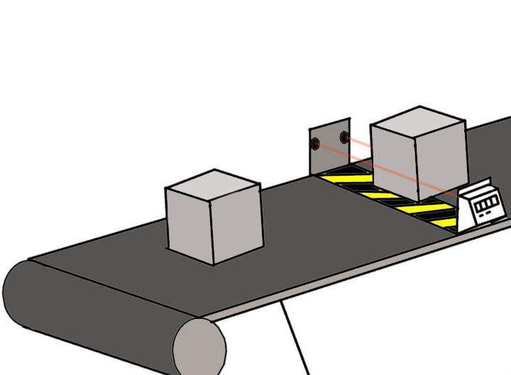
Introducing the application: a counter with IR technology
The distance from the object is very important and in some cases the IR sensor is not suitable for these applications. If the distance from the object is greater than 20-30cm, the ultrasonic sensor can be a better choice.
We need to know when the IR sensor changes its state from HIGH to LOW and count how many times this transition happens: this is called state change detection. For more information on operation principle of the IR sensor we suggest to read the main article.
A bidirectional counter
High end counters use sophisticated hardware for counting process. Our project is a simple objects counter based on Arduino and two IR sensors. More in details, it is a 0 to 9 counter in which the first sensor is used to count ingoing people, the second those outgoing. The difference (IN – OUT) is shown on a 7-segments display.
Hardware description: a 7-segments display
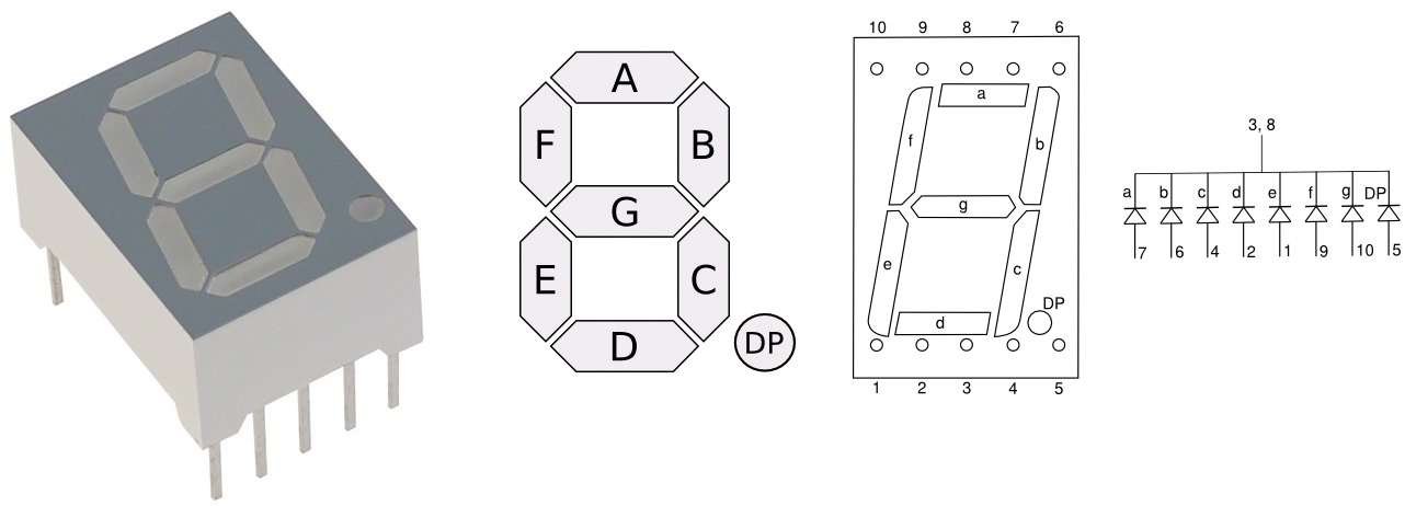
Focusing on the 7-segments display SMA42056, this is an electronic component designed to for display numbers and often used in digital clocks, electronic meters and other kind of numeric displays.
The SMA42056 model is a common cathode 7-segments display with eventually an additional segment called decimal point or simply dot, represented by the P letter (See Fig.2), which is used for displaying non-integer numbers. Each segment is just a simple LED, and is often represented by the letters from A to G. The 7-segment display doesn’t embed a series resistor for each LED and driving them with a constant DC voltage can permanently damage junctions: to avoid this we will use a series resistor of 220Ω for each LED.
Demo Explained: A bidirectional counter
What it has to do and what is the necessary
This proposed demo counts non-transparent objects which are traversing two IR gate: the first gate produce an increment on a total counter, the second produce a decrement. Since our simple demo uses a one digit display our application checks that two things have occurred:
- The counting must not be represented by a negative number;
- The counting must not be represented by a number greater than 9;
Our BOM (Bill of Materials) is:
- Arduino UNO board;
- 2 x IR sensor fc-51;
- 1 x 7-segments display SMA42056;
- 8 x R = 220Ω.
From schematic to code
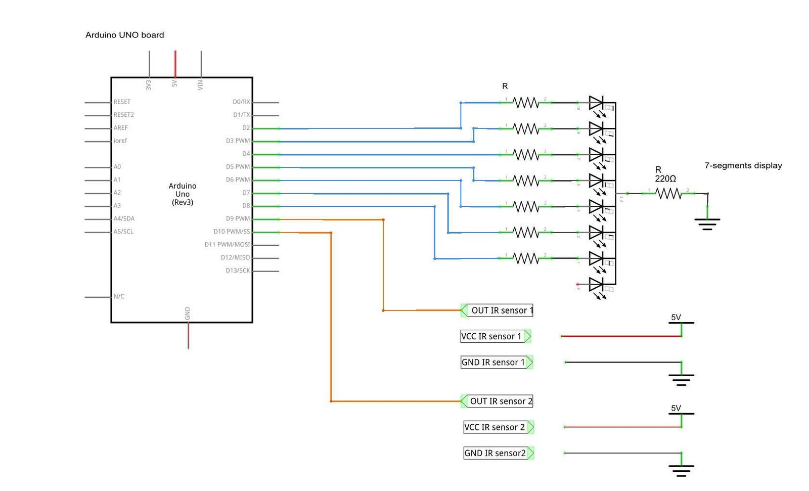
To drive the 7 segment display we need for 7 digital output PINs as shown in Fig.4. We also need to read information from our two IR sensors. This requires to use 9 digital pins.
In our case we have used the pin from D2 to D10 of our Arduino. To make code much more clear we have defined PIN numbers assigning them a proper name. Note that, parameters which are constant at run time and, consequently, defined at compile time, we are using preprocessor directives.
Using the “define” directive we are not only reducing memory occupation, but also optimizing the program execution.
We are defined the digital pins (from D2 to D8) we are going to use to drive our display as DISP_PIN_x (x from 0 to 6). The two output pins of the IR sensors (D9 and D10) has been defined as IR1 and IR2.
/*===========================================================================*/
/* PIN-map.                                                                  */
/*===========================================================================*/
#define DISP_PIN_0              2        /* digital pin input for segment A  */
#define DISP_PIN_1              3        /* digital pin input for segment B  */
#define DISP_PIN_2              4        /* digital pin input for segment C  */
#define DISP_PIN_3              5        /* digital pin input for segment D  */
#define DISP_PIN_4              6        /* digital pin input for segment E  */
#define DISP_PIN_5              7        /* digital pin input for segment F  */
#define DISP_PIN_6              8        /* digital pin input for segment G  */
#define IR1                     9        /* digital pin input for ir sensor  */
#define IR2                     10       /* digital pin input for ir sensor  */
We have also defined some additional constants:
- NUMB_OF_PRESET, that is number of pre-set stored in our look up table (i.e. 10 since we are going to use digits from 0 to 9);
- NUMB_OF_SEGMENTS, that is the display segments we are using;
- MAX_NUMB, that is the high counting range limit.
/*===========================================================================*/
/* Constant values                                                           */
/*===========================================================================*/
#define NUMB_OF_PRESET          10       /* Available preset                 */
#define NUMB_OF_SEGMENTS         7       /* Available segments               */

#define MAX_NUMB                 9       /* High counting range limit        */
There are some other constant value declared in our code, anyway for ease of use we preferred to store them into an bidimensional array called displaySEG is a look up table: in other words it is an collection of PIN preset required to show a certain digit on the display.
While the rows indicate the digit, the columns represent each segment (LED) of the display. For example, to display the number 0, all the segment except G must be set as HIGH (see Fig.2). The first element of our array stores the configuration required by each DISP_PIN to display a 0. So we can use the array displaySEG[0] in a loop to set each DISP_PIN according to our preset and obtain our 0.
/*===========================================================================*/
/* Lookup table.                                                             */
/*===========================================================================*/
const byte displaySEG[NUMB_OF_PRESET][NUMB_OF_SEGMENTS] = {
        /*  A     B     C     D     E     F     G            */
        { HIGH, HIGH, HIGH, HIGH, HIGH, HIGH,  LOW }, /*  0  */
        {  LOW, HIGH, HIGH,  LOW,  LOW,  LOW,  LOW }, /*  1  */
        { HIGH, HIGH,  LOW, HIGH, HIGH,  LOW, HIGH }, /*  2  */
        { HIGH, HIGH, HIGH, HIGH,  LOW,  LOW, HIGH }, /*  3  */
        {  LOW, HIGH, HIGH,  LOW,  LOW, HIGH, HIGH }, /*  4  */
        { HIGH,  LOW, HIGH, HIGH,  LOW, HIGH, HIGH }, /*  5  */
        { HIGH,  LOW, HIGH, HIGH, HIGH, HIGH, HIGH }, /*  6  */
        { HIGH, HIGH, HIGH,  LOW,  LOW,  LOW,  LOW }, /*  7  */
        { HIGH, HIGH, HIGH, HIGH, HIGH, HIGH, HIGH }, /*  8  */
        { HIGH, HIGH, HIGH, HIGH,  LOW, HIGH, HIGH }, /*  9  */
};
We need for additional variables which are the status of the IR sensors named as IRx_out (with x 1 or 2), a variable to store the counting value and a generic i used in loops.
int IR1_out = HIGH; /* Avoiding initial false detections.    */
int IR2_out = HIGH; /* Avoiding initial false detections.    */
int counter = 0;
int i = 0;
Functions explained
setDisplayValue()
This function writes a number from 0 to 9 on the display. More in details, the parameter n represent the number to show on our display. Note that n%10 is required to avoid eventual buffer overflow.
void setDisplayValue(int n) {
  for(i = 0; i < NUMB_OF_SEGMENTS; i++){
    digitalWrite(DISP_PIN_0 + i, displaySEG[n % 10][i]);
  }
}
initDisplay()
This is not a function but a macro which ridefine setDisplayValue passing 0 as argument. This macro is used to reset display on start-up. Note that using the preprocessor directives we are still optimizing memories and performances avoiding to create an additional activation record.
#define initDisplay() setDisplayValue(0)
increaseAndDisplay()
This function increases the counter and updates the display. Note that, if the counter becomes greater than MAX_NUMB it wraps to 1.
void increaseAndDisplay() {
  counter++;
  if(counter > MAX_NUMB) {
    counter = 1;
  }
  setDisplayValue(counter);
}
decreaseAndDisplay()
This function decreases the counter and updates the display. Note that, if the counter is equal to 0 it does nothing: in this way we are avoiding negative numbers.
void decreaseAndDisplay() {
  if(counter) {
    counter--;
    setDisplayValue(counter);
  }
}
Main code
setup()
The setup() sets pin modes: IRx as inputs and DISP_PIN_x as output. Than it call initDisplay() showing a zero on our SMA42056.
void setup() {
  Serial.begin (9600);
  pinMode(IR1, INPUT);
  pinMode(IR2, INPUT);
  /* Setting Display related PIN as OUTPUT */
  for(i = 0; i < NUMB_OF_SEGMENTS; i++){
    pinMode(DISP_PIN_0 + i, OUTPUT);
  }
  initDisplay();
}
loop()
The loop reads IR statuses saving in them into IRx_out. When an non-transparent object is detected by an IR its value is LOW. If the “entrance” IR detects an object loop calls increaseAndDisplay(), if the other IR detects an object the loops calls decreaseAndDisplay(). Note that a delay is required to avoid false detections.
void loop() {
  IR1_out = digitalRead(IR1);
  IR2_out = digitalRead(IR2);
  if(IR1_out == LOW) {
    increaseAndDisplay();
    delay(500);
  }
  if(IR2_out == LOW) {
    decreaseAndDisplay();
    delay(500);
  }
  delay(100);
}
Download for Arduino IDE
This demo has been tested under Arduino IDE 1.6.7:
The project is looking nice.
great project and I really would like to say thank you. I am am working on counting the number of people in a vehicle and if it is beyond the limit a dc motor will be activated for controlling the power transmission. what is the appropriate sensor for the counting?
Hi everyone I need a help
my project is like this
The project like this, 3 ir sensor senders and receivers were put to count people who are in the room if the number of them is more than 4 for example the DC motor must turn off 3
Senders and 3 receivers for more accurate let’s say that the first sensor is (A) the second (B) and the third (C)if A works fist then B then C we can assume that the person is entering the room but if C then B then A then he is existing, and if the number of people in the room in more than 4 the DC motor which is connected with a transistor must turn off
so please if any one can help me to write the arduino code ?
// I don’t want to use an LCD or monitor . just if the number is more than 4 the DC motor must turn off
any help ?
Hi Mohannad,
thanks for you comment. I don’t think that author would be able to provide a code for your project. BTW, if you ask something more specific we can help.
how about a 2 digit 7 segment display using 2 shift registers?
Hi, it is possible. Note that there are specific chip which allow to drive up to 8 digit like MAX7219 already introduced here:
MAX7219-8×8 Display,
MAX7219-8×8 7-Segment Display
im using a 2 single digit 7 segment display , 2 shift registers(74hc595n) and two fc-51 IR sensors.
im having a hard time doing the code because it turns out that there is a minor error. it is already counting up and down but when it stop at a certain number (ex.55) it is moving back and forth like ( 55, 54 , 55, 54, 55 etc.);
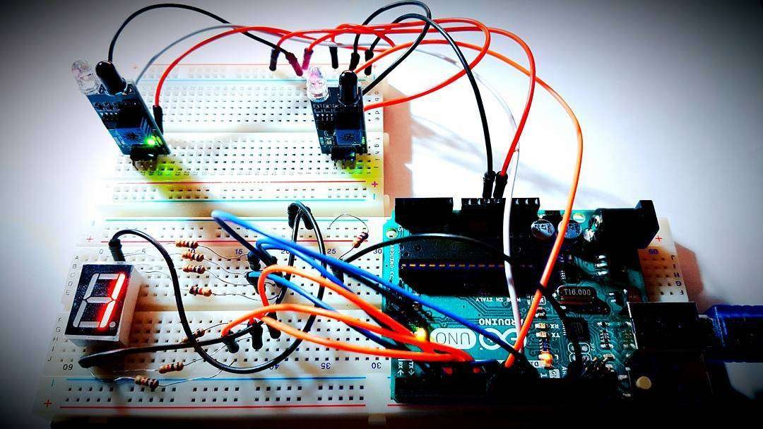
hello Rocco , good job i really appreciate it but can you please upload another photo discussing how you connect the arduino board with the sensors and 7 segments ???
Hi Ahmed,

thanks but this is not one of my articles. The author is Carmine Forino. BTW the connections are schematised in this image:
Is it unclear?
i’m trying to find this pins on the right hand side of arduino board but the one i have contains pins from 0 to 13 on the right side
Sorry for this very late reply. I have missed this comment. This way to enumerate PIN (A0~A5, D0~D13) is standard for that board which are equipped with Arduino Uno Rev3 Connector like Arduino Uno, Arduino Mega or STM32 Nucleo
if you make it more clear i really appreciate that
Hi, how do you do when a person break in the front at sensor?
Hi Julio,
note that this is just a small experiment not a full working solution. BTW, a solution could be to create a field of sensors for each gate. This solution is used in industrial electronic gates for safety. Of course, in case of safety applications, Arduino is not the adopted solution.
Hello. My partner Alex and I are in a dual-enrollment engineering class at our high school, and are attempting to utilize a modified version of your code (and, of course, crediting you as a source) for a very important end-of-year project. However, we are unsure if our setup is correct, and the image of yours is obscured by shadow and taken from an angle; its lack of clarity makes us unable to cross-check it against our own. Do you think that you could provide us with a clearer image for our purposes? Thank you.
Hi, there is a schematic attached. Is it unclear? I had a similar comment. Please provide a feedback so we can figure out where is the problem and find out a solution.
I appreciate the schematic, though I have a bit of trouble translating it to its equivalent on the physical board. I can interpret it somewhat, but when it comes to actually applying the information presented within the schematic to the setup itself, our inexperience with both leads to our inevitable failure. What would be most helpful, I think, would be a clearer image of the physical setup, if one is available. Thank you for your help!
What board are you using?
When I try to upload the code an error occurs highlighting the, #define initDisplay setDisplayValue(0) segment saying
“exit status 1
void value not ignored as it ought to be”
what is wrong and what should I do
Hi,
it was a missing parenthesis. I have fixed and updated the file.
Hello,
Can we use IR tcrt 5000 as an object counter using this code?
Hi,
the IR tcrt 5000 has not the Schmitt trigger nor the mounting circuit. It is required a little bit of electronics to use it with this code. The easy way is to change the code and use Analog read.
What kind of power supply did u use to active the arduino??
Hi,
the USB cable should be enough
Thanks for replying, like maybe im doing the same project like this. But can i use dc adapter as a power supply??
Hello, can you send another photo clear from bird eye point of view. My partner and I have to do a project, Object counter, and we find yours very interesting. But we cannot seem to see the circuit board clearly when connecting the jumpers.
Hi Elizabeth. The circuit is not mounted anymore and this article is very old.BTW, you should always rely on schematics. In this case it is reported in figure 4.
hello, I’m having problems with the counter stuff. I’m using 3 IR proximity sensors with which when the three sensors were triggered (paper blocking the path) at the same time, it must count as 1, and until the paper has been out of the way the count must still be one. The thing is, the counter kept on increasing one at a time at a steady pace even if the paper blocking the path was just motionless under the IR sensors. I think I got the codes wrong. I’m hoping you could help me out 🙂 Thanks in advance!
Hi Elaine,
thanks for asking. I would use a static variable. For instance the next code will clarify my statement:
/* This variable is global in this source file and in all the files whichincludes it. */
static bool flag = TRUE;
void setup() {
/* here goes the initialization code. */
}
void loop() {
/* Getting status from the three IRs. */
IR1_out = digitalRead(IR1);
IR2_out = digitalRead(IR2);
IR3_out = digitalRead(IR3);
/* If all the IR have detected something and flag is true. */
if((IR1_out == LOW) && (IR2_out == LOW) && (IR3_out == LOW) &&
(flag == TRUE)) {
/* Prevents another increase until flag is restored to true. */
flag = FALSE;
/* Increases the counter and displays the value. */
increaseAndDisplay();
}
/* If one of the IR is low. */
if((IR1_out == HIGH) || (IR2_out == HIGH) || (IR3_out == HIGH)) {
/* Restore the flag. Next detection will be counted. */
flag = TRUE;
}
delay(100);
}
Thank you so much for your help 😀
hey there ..
i was trying the same project but need some help in the code ..
your link for code here is not working can you please send me the code asap….
Dear, on our side the link is working properly. All we have is shared in this article
HI! How can we use the same project for a greater distance, can you help me with the code for ultrasonic sensor
Hello there,
we have a great article about ultasonic sensor with STM32 here.
Detecting obstacles using an ultrasonic sensor HC-SR04
instead of bidirectional. what if only one enterance is there? i need to find how many persons in the room
use only the increase