ARM Cortex clock tree 101: Navigating clock domains
Introduction
In embedded systems, the clock is an essential element responsible for synchronizing all the different parts of the system and ensuring that they work together correctly. Modern microcontrollers are complex systems having different domains running often at different speeds. However, the clock tends often to be generated from the same source so that all the domains are synchronized to one another.
The clock configuration not only determines the speed of the entire system but also the achievable speed of each peripheral. For instance, when configuring the baud rate of an SPI peripheral in an STM32 microcontroller, it is crucial to first understand the clock domain to which the SPI belongs and the configuration of that specific clock tree branch.
In this article, we will explore the clock tree and clock domains of ARM Cortex-based microcontrollers. We will discuss the different clock sources, such as internal and external, high and low-speed oscillators, and the role of PLLs in clock generation. Furthermore, we will delve into the AHB and APB clock domains and explain how to determine the clock speed fed to a peripheral on a specific microcontroller, providing you with a comprehensive understanding of clock management in embedded systems.
The clock tree
In microcontrollers, the clock is generated and distributed to ensure synchronization throughout the entire system. Typically, the same clock source feeds everything, from the CPU and memory to the peripherals, to ensure that all parts of the system operate in unison. The clock distribution system is often called Clock Tree because of its ramification from the source down to the last peripheral.
The clock signal is typically generated using an internal or external oscillator in combination with a Phase-Locked Loop (PLL) to multiply the original clock to a higher frequency. The Clock Tree is organized into different clock domains, which are groups of circuitry that share the same clock speed. These clock domains are typically cascaded to one another through prescalers, which divide the clock signal to generate the appropriate clock frequency for each domain.
By dividing the clock signal into different domains, the Clock Tree can accommodate the different clock speeds required by the CPU, memory, and peripherals. This allows the system to operate efficiently and effectively, with each part of the system receiving the appropriate clock signal.
Clock generation
When it comes to clock generation in microcontrollers, there are two main considerations to keep in mind:
- Higher clock speeds generally result in higher power consumption. Therefore, it is important to choose a clock speed that is appropriate for the application in question. In some cases, a low-speed clock may be sufficient and can help to conserve power.
- Clock signals generated using integrated circuitry are not always stable over temperature, supply voltage, and aging. For precise timing, crystal oscillators are often used instead of integrated circuits. However, crystal oscillators require external components and are typically larger than integrated circuit oscillators.
To provide flexibility, microcontrollers often feature a variety of clock sources, including internal and external high-speed and low-speed oscillators. These oscillators can generate clock frequencies ranging from a few kHz (e.g., a typical speed of 32.768 kHz) up to several tens of MHz (e.g., depending on the manufacturer, ranging between 8 and 66 MHz). These oscillators can be completely integrated into the microcontroller (internal oscillators) or can require a couple of external components (external oscillators).
Generally, oscillators alone may not be sufficient to attain the clock speed at which a microcontroller’s CPU operates. As a result, modern microcontrollers also rely on PLLs, feedback systems capable of generating a higher-frequency clock signal from a lower-frequency clock source, to meet the necessary clock speeds.
The clock tree presents numerous options (in the form of bitfields into registers) for selecting the source to generate the main clock and determining its distribution. This enables designers to choose the clock source that best fits their application, allowing them to strike a balance between performance and power consumption as needed.
In the following sections, we will discuss the pros and cons of the different types of oscillators and we are going to introduce the PLL.
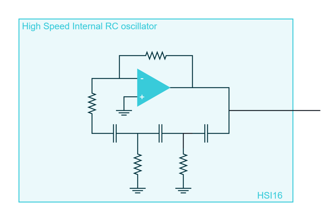
Internal RC oscillators
RC oscillators are circuits that combine an inverting amplifier with a feedback network made up of resistors and capacitors. One advantage of RC oscillators is that they can be designed using integrated technology and embedded within microcontrollers, making them a popular choice for internal oscillators. However, the frequency stability of RC oscillators can vary significantly over temperature, supply voltage, and aging, typically up to several percent. For this reason, RC oscillators are not commonly used as a reference clock source in systems where precise timing is required. To improve the accuracy of an RC oscillator, temperature compensation or more precise resistor and capacitor components can be used.
Most modern microcontrollers have a high-speed internal oscillator that runs at a speed in the range of a few to several dozen MHz as the primary clock source immediately after the power-on reset. For example, the STM32 microcontroller series from STMicroelectronics offers a High-Speed Internal (HSI) oscillator that can run at 8 MHz or 16 MHz, depending on the specific model. The MAX32 microcontroller from Analog Devices offers an Internal Fast RC oscillator that can run at up to 8 MHz. The SAM microcontroller series from Microchip offers an Internal RC oscillator that can run at up to 48 MHz.
Along with the high-speed oscillator, many microcontrollers also offer a secondary low-speed oscillator that runs at a characteristic frequency of 32kHz. For example, the STM32 microcontroller series offers a Low-Speed Internal (LSI) oscillator that runs at 32.768 kHz. The MAX32 microcontroller offers an Internal Low-Power RC oscillator that can run at up to 31 kHz. The SAM microcontroller series offers a low-power internal oscillator that can run at up to 32 kHz.
The low-power clock is typically used in low-power applications, such as keeping the Real Time Clock (RTC) peripheral awake and generating periodic interrupts to wake up the system from sleep mode.
Crystal oscillators
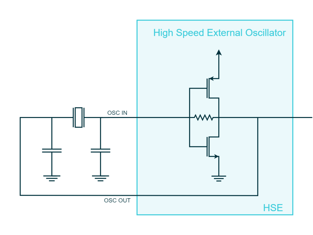
In some applications, the low accuracy of RC oscillators is not sufficient, and more precise timing is required. In these cases, a crystal oscillator can be used to provide a stable and accurate clock source. Crystal oscillators work based on the resonance of a quartz crystal, which vibrates at a very precise frequency when an electrical charge is applied to it. When it comes to microcontrollers, these oscillators are implemented typically using the Pierce oscillators topology, which combines a CMOS inverter with two capacitors and a crystal. However, as the crystal cannot be integrated into the microcontroller die, two pins on the microcontroller are required to connect to external components to complete the circuit.
There are many different types of crystals that resonate at different frequencies, with typical values of 8, 16, 32, and 48 MHz. The range of accepted crystal frequencies depends on the specific microcontroller model. For example, the STM32 microcontroller series from STMicroelectronics can accept external crystals with frequencies ranging from 4 MHz to 26 MHz for what is called HSE or High-Speed External clock. The MAX32 microcontroller from Analog Devices can accept external crystals with frequencies ranging from 4 MHz to 20 MHz. The SAM microcontroller series from Microchip can accept external crystals with frequencies ranging from 3.57 MHz to 20 MHz.
In addition to high-frequency crystal oscillators, some microcontrollers also support low-frequency external quartz crystals for low-power applications. These low-speed crystals typically operate at frequencies of 32 kHz or lower and are used once more for low-power applications where accurate timing is relevant.
The Phase-Locked Loop
The Phase-Locked Loop (PLL) is a feedback system that can generate a clock signal running at a frequency that is an integer multiple of a lower-frequency clock source. In essence, the PLL can utilize an internal or external high-speed oscillator running at tens of MHz (e.g., 8, 16, 32 MHz) as an input to produce a higher-speed clock operating at hundreds of MHz (e.g., 100, 200, 400 MHz).
To better understand how PLLs function as clock multipliers, it’s important to delve into their inner workings. The PLL consists of three main components: a phase detector, a loop filter, and a voltage-controlled oscillator (VCO). These components work together in a feedback loop to create an output clock signal with a frequency that is an integer multiple of the input clock frequency.
To understand the working principle of a PLL let us consider the following block diagram
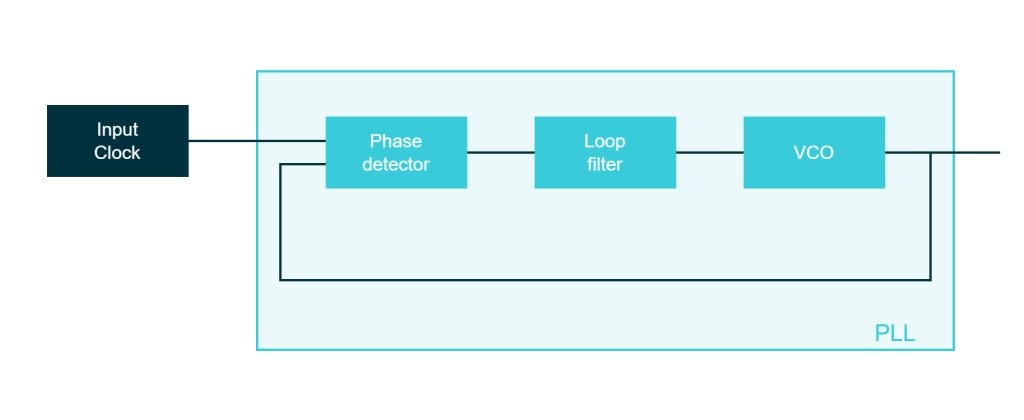
The phase detector compares the phase of its two input. generating an error signal proportional to the phase difference between the two signals In this case these inputs are the reference clock (black box) and the signal coming from the feedback loop that, in this case, it happens to be the output clock. The error signal is then filtered by the loop filter, which smooths out rapid fluctuations and produces a control voltage. The control voltage is then fed to the VCO, which adjusts its output frequency based on the input control voltage. As the VCO’s output frequency is fed back into the phase detector, the PLL continuously works to minimize the phase difference, effectively locking the output clock’s frequency to the frequency of the input signal.
This “dummy” PLL is now producing an output signal at the same speed of the input clock. However, when the PLL is used as a clock multiplier, the feedback signal is divided by a specific integer value, known as the division factor, before being fed back into the phase detector.
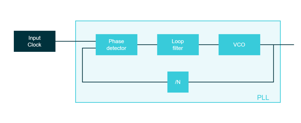
This division factor is what ultimately determines the multiplication factor of the PLL. Indeed the signals in input to the Phase Detector will run at the same frequency but the output signal is going to be equal to the input signal multiplied by N. For example, if the input clock frequency is 10 MHz and the division factor is set to 4, the PLL will lock onto an output frequency of 40 MHz (i.e., 10 MHz x 4).
It is crucial to emphasize that the input and output clocks of a PLL are closely interconnected, and the quality and stability of the input clock directly affect the output clock. This means that any errors or variations in the input clock will be proportionally reflected in the output clock. For instance, if a 16 MHz RC oscillator with a total error of 5% over the temperature range is multiplied using a PLL to reach 160 MHz, this output clock will still exhibit an error of 5%.
In other words, the PLL maintains the essential properties of the input clock, including its inherent stability and accuracy, while generating a higher-frequency output clock. As a result, it is important to ensure that the input clock source is of high quality and stability, especially in applications where precise timing and synchronization are crucial.
In the context of microcontrollers, the PLL can be configured to have multiple clock sources and a prescaler for the input and output clock as shown in the next block diagram representing the main PLL of the STM32F4
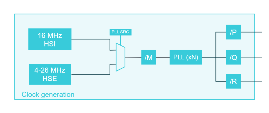
Some microcontrollers may have multiple PLLs to support different clock requirements for various peripherals. Indeed the main clock can be scaled by dividing it by power-of-two numbers and in some special cases by integer numbers. This means that a peripheral can run only at a speed that is submultiple to the main clock. This can become problematic if a peripheral requires a clock frequency that is not an integer fraction of the main clock. In these cases, a secondary PLL can be used to generate a clock signal that meets the specific requirements of the peripheral.
For example, the original STM32F407 is able to run up to 180 MHz but, having only a PLL, its speed need to be lowered to 168MHz if we want to use the USB peripheral that requires 48MHz. The issue was addressed in a reiteration of the family known as STM32F469 which has multiple PLL and one is dedicated to the generation of the clock for the USB peripheral. Despite having multiple PLLs, all of the clocks in the microcontroller remain synchronized because they use the same clock source, such as the High-Speed External (HSE) or High-Speed Internal (HSI) oscillator.
Buses and clock domains
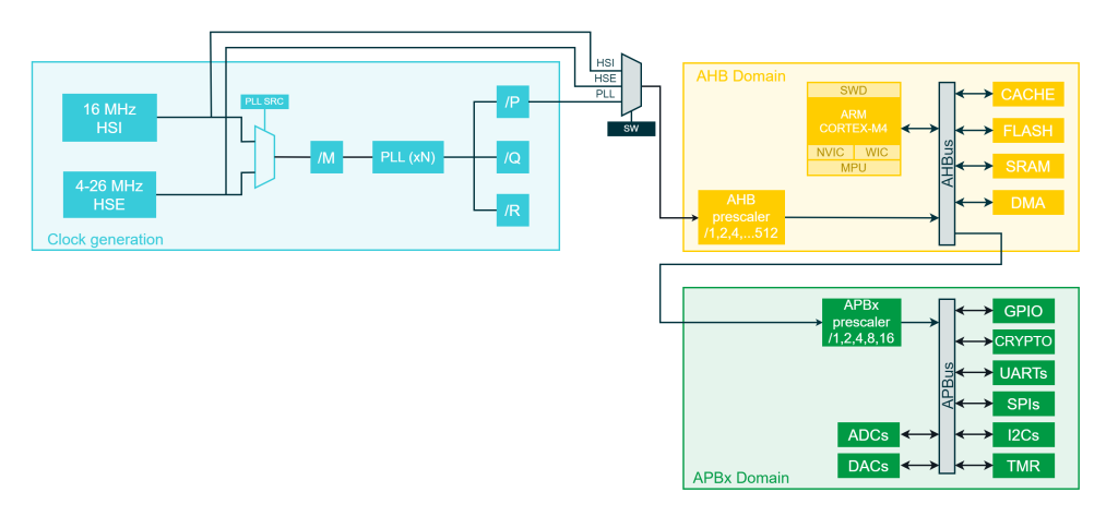
A microcontroller is essentially a collection of logic circuits that need to exchange data in a synchronized manner. For instance, the CPU, DMA, and memories of a microcontroller must operate at the same frequency to enable efficient data transfer. In an ARM Cortex-M MCUs, this activity is supported by the Advanced High-performance Bus (AHB), a bus designed for high-performance communication that runs at the highest speed available in the system, typically driven by the clock generated by the PLL. As all the entities connected to this bus operate at the same speed, the AHB is often referred to as a clock domain.
Connected to the AHB are subdomains running at slower speeds, such as the Advanced Peripheral Bus (APB). APB is designed for connecting lower-speed peripherals and components that do not require high bandwidth. It focuses more on power efficiency and simplicity, making it ideal for managing communication with slower peripherals in the system.
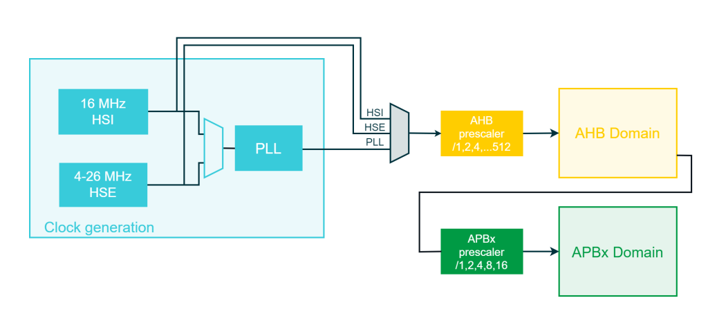
In general, clock distribution in an ARM Cortex starts with clock generation. A multiplexer and a prescaler enable the selection of the clock source for the AHB. From there, the clock is branched to the various entities connected to the AHB and to the APBs. Each APB has a prescaler that scales the input clock for all the peripherals belonging to that domain.
Determining CPU and Peripheral Speeds
CPU
So how at what speed is running the CPU of my microcontroller? Looking back at what we wrote so far, it should be clear that the speed of the CPU is the same as the AHB domain. To determine this we need to figure out which source is used for the AHB and the AHB prescaler. If the source of the AHB is the PLL then it is necessary to calculate at which speed the PLL runs.
The clock tree we have discussed so far is for the STM32F469 used in the ADI SDP-K1. The following code initializes the clock tree in a ChibiOS-based project. While the code may look different when using another embedded library, the underlying logic remains applicable. Let’s use this example to determine the CPU speed in this case:
/*
 * HSE speed from the board files.
 */
#define STM32_HSECLK                        8000000U

/*
 * Excerpt of the mcuconf.h needed to calculate the AHB and APBx speed.
 */
#define STM32_SW                            STM32_SW_PLL
#define STM32_PLLSRC                        STM32_PLLSRC_HSE
#define STM32_PLLM_VALUE                    8
#define STM32_PLLN_VALUE                    360
#define STM32_PLLP_VALUE                    2
#define STM32_HPRE                          STM32_HPRE_DIV1
#define STM32_PPRE1                         STM32_PPRE1_DIV4
#define STM32_PPRE2                         STM32_PPRE2_DIV2
We can observe that the main clock switch is set to PLL (STM32_SW set to STM32_SW_PLL) and the prescaler of the AHB is set to 1 (STM32_HPRE set to STM32_HPRE_DIV1). This indicates that the CPU runs at the speed of the PLL. Referring back to the PLL block diagram, the formula is:

Since the source here is set to HSE (STM32_PLLSRC set to STM32_PLLSRC_HSE) and the speed of the external crystal is 8 MHz, as stated by the constant STM32_HSECLK, we have:

Thus, the entire AHB domain, including the CPU, DMA, and memories, operates at 180 MHz.
Peripheral
What about a peripheral? Peripherals are organized into APB domains, and a microcontroller with many peripherals may have multiple APB domains. The first step is to determine which APB domain a specific peripheral is connected to and then identify the prescaler of that APB. Since the APB is driven by the AHB, the speed of the peripheral will be a fraction of the CPU speed, depending on the APB prescaler value.
For example, let’s examine the SDP-K1 and determine the speed of the clock fed to the SPI1. The first thing to do is to note that the STM32F469 has two APBs, namely APB1 and APB2. The primary question, then, is which APB the SPI1 is connected to. To find this information, open the User Guide for the STM32F469 and check the Reset and Clock Control chapter. Ideally, you would find a diagram that shows the complete clock tree, but if that is not available, you can use an alternative approach by checking the bitfields of the clock enable registers. These registers contain information about which peripherals are connected to which APB.
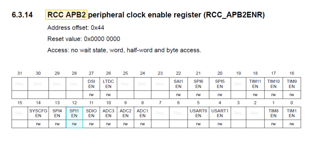
In this case, the SPI1 is connected to the APB2 that according to the configuration in the mcuconf is prescaled by 2 (STM32_PPRE2 set to STM32_PPRE2_DIV2).
/*
 * HSE speed from the board files.
 */
#define STM32_HSECLK                        8000000U

/*
 * Excerpt of the mcuconf.h needed to calculate the AHB and APBx speed.
 */
#define STM32_SW                            STM32_SW_PLL
#define STM32_PLLSRC                        STM32_PLLSRC_HSE
#define STM32_PLLM_VALUE                    8
#define STM32_PLLN_VALUE                    360
#define STM32_PLLP_VALUE                    2
#define STM32_HPRE                          STM32_HPRE_DIV1
#define STM32_PPRE1                         STM32_PPRE1_DIV4
#define STM32_PPRE2                         STM32_PPRE2_DIV2
In other words, any peripheral connected to APB1 is fed with a clock that runs at 45 MHz (i.e., 180 MHz divided by 4), and any peripheral connected to APB2 is fed with a clock that runs at 90 MHz (i.e., 180 MHz divided by 2). It is important to note that this does not necessarily mean the peripheral is running at that exact speed, as each peripheral typically has its own internal prescaler for more granular control. However, the speed of the main clock does influence the maximum attainable speed for a peripheral.
Conclusions
To conclude, understanding the clock tree and clock domains in ARM Cortex-based microcontrollers is crucial for the proper functioning and optimization of embedded systems. This article has provided insights into the various clock sources, including internal and external oscillators, and the significance of PLLs in generating higher-frequency clock signals. We have also explored the AHB and APB clock domains and their impact on the performance of different components within a microcontroller.
By comprehending the clock configuration and its influence on the system and peripheral speeds, designers can make informed decisions when configuring and optimizing their embedded systems. This knowledge is particularly vital when dealing with peripherals, as their maximum attainable speed is directly impacted by the clock tree configuration.
Thank you. I found this to be very helpful.
Very nice and helpful explanation! It was very useful for my current projects based on
ST Cortex-M7 MCUs . Thank you very much!
Thanks So
Nice explanation, very helpful. Thanks a lot!
Thank you for commenting
Great explanation keep up the good work!!