
Breadboards explained: tips and tricks
Introduction
Breadboards are an essential tool for anyone interested in electronics. They allow you to quickly connect through-hole components together and experiment with electronics. In this article, we will explore the different types of breadboards, including solderless breadboards and perfboards.
While all types of breadboards have their pros and cons, our focus will be on solderless breadboards. These breadboards can be incredibly useful for quick prototyping, but their intrinsic instability can sometimes generate confusion for beginners. However, with proper usage and some tips and tricks, solderless breadboards can be an amazing tool for quick evaluation.
So, whether you are new to electronics or an experienced tinkerer, this guide will provide you with useful tips and tricks to master solderless breadboards.
What are breadboards
Breadboard is a broad term that refers to some flexible tools used in electronics for prototyping and experimenting with circuits. While the term may refer to different types of boards, the two most common types are solderless breadboards and perfboards.
A solderless breadboard consists of a plastic board with a grid of interconnected metal strips or spring clips that allow for the temporary connection of through-hole electronic components without the need for soldering. Solderless breadboards provide a quick and easy way to test and modify electronic circuits before creating a permanent version on a printed circuit board. However, the connections on a solderless breadboard can sometimes be mechanically unstable, especially when using large components or high-frequency circuits, and they are not always the best choice for long-term durability.
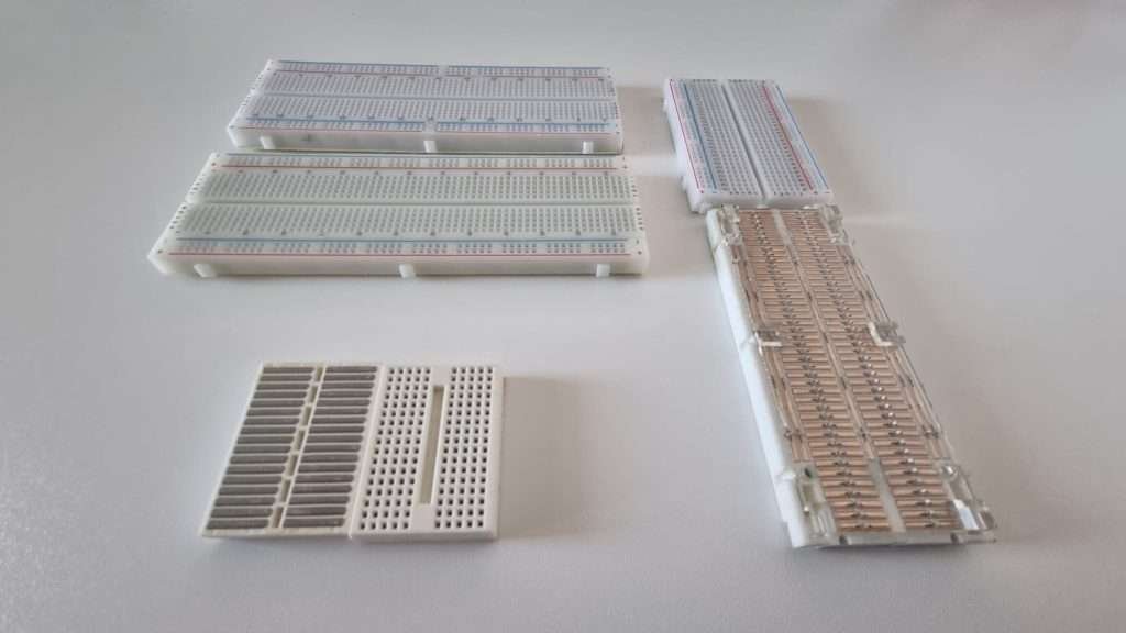
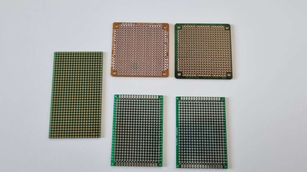
In contrast, a perfboard is a type of circuit board with pre-drilled holes that allow for the insertion of through-hole components. Unlike a solderless breadboard, components on a perfboard must be soldered in place. While perfboard can be more time-consuming to create and modify circuits, it is a good option for those who want to create more permanent circuits.
In the following sections, we will mainly focus on solderless breadboards, which can be used without the need for soldering and are reusable. This is ideal for the circuits we will be proposing through PLAY Embedded, which are small and designed for learning purposes. As a result, a more permanent solution such as perfboard is not necessary.
Anatomy of an MB-102 Breadboard
Solderless breadboards come in a variety of sizes and shapes, but one of the most common is the MB-102. This breadboard features 830 connection points and is easily recognizable by its distinctive rectangular shape. The board also features power rails on both sides, which are typically marked in blue and red.
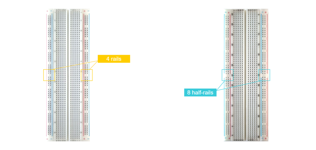
There are two variants of the MB-102 breadboard:
- The first variant features four vertical supply rails that run from top to bottom for the entire breadboard.
- The second variant features eight half-rails as the rails are split at the midpoint.
These two variants can be distinguished by the lines depicted on the breadboard. In the four-rail version, the lines are continuous, indicating that the various holes are all connected together. In contrast, the lines in the half-rail version are split in the center, indicating the separation between the two halves of the power rails.
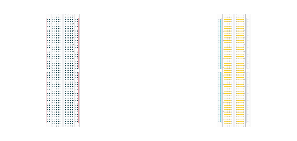
The following diagram shows the connection of the four power-rails variant of the MB-102.
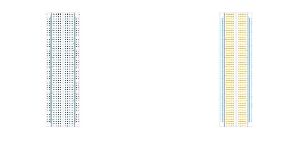
The four power rails on the MB-102 breadboard feature 50 connection points each and run vertically from top to bottom across the entire board. These power rails can be connected to a power supply to facilitate the distribution of the power source across the breadboard. The horizontal connections on the board are organized into two large columns of rows, which are not connected to each other. This distribution is particularly suitable for hosting DIP-format chips in the center of the breadboard.
The half-rail version is pretty similar with the difference that the rails are split at the midpoint
Choosing a power supply
The HW-131
The MB-102 breadboard has a companion board called the HW-131, which is designed to fit on the power rails of the breadboard and supply them with a selectable voltage of either off, 3.3V, or 5V. The HW-131 is a cheap PCB that can be stacked onto the breadboard, making it a convenient addition to any electronics project
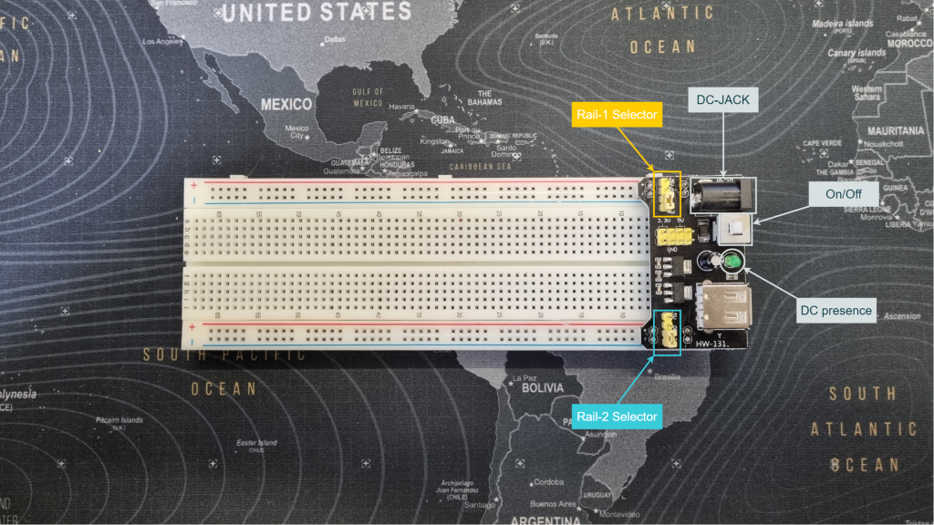
While the HW-131 board is an affordable option, it is not known for its reliability. There have been reports of unreliability with this type of board when powered with 12V. For best results, it is recommended to power the board with a wall power supply that has an output in the range of 7.5V to 9V. While more detailed analyses on this topic are available on the internet, this range of voltage has been found to be optimal for powering the board and ensuring its proper functioning.
The ADALM2000
For those seeking a more powerful and reliable option, the ADALM2000 can be a suitable alternative. This kit is equipped with two programmable power supplies, a two-channel arbitrary function generator, a two-channel USB digital oscilloscope, and a 16-channel logic analyzer. The tool requires a USB connection to a PC and comes with a suite known as Scopy. With its comprehensive set of tools, the ADALM2000 is not just a power supply, but a versatile, pocket-size, electronics lab.
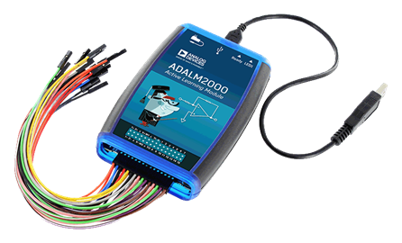
Interestingly, the ADALM2000 kit is designed to be a learning module and comes with a dedicated wiki that is full of examples and exercises. These resources can help you to gain confidence with the basics of electronics and provide you with opportunities to conduct experiments and further your understanding of electronics principles.
Example of connections
When using through-hole components on a solderless breadboard, the general approach is to connect the two leads of each component to two different rows on the board. If two components need to be connected in series, they share one row on the board. The rows that need to be powered can be connected to the power rails using jumper wires. When using jumper wires, it is important to keep them short and tidy to avoid signal interference and messy circuit layouts.
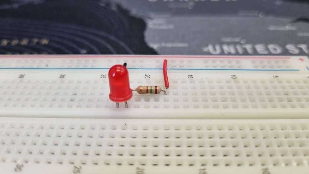
As an example, let us consider a simple circuit that includes a red LED connected in series with a 150Ω resistor, with the circuit branch closed on the 3.3V rail. This circuit can be represented visually with the following diagram:
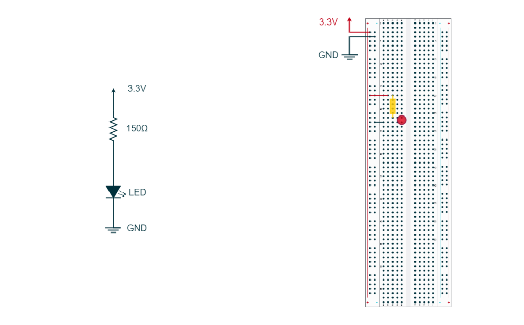
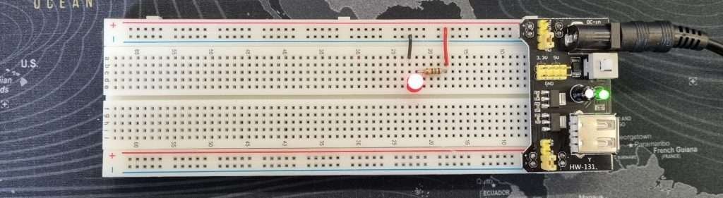
In this case, the left rails of the breadboard have been connected to 3.3V and ground, and the power has been distributed to the appropriate rows on the right side of the breadboard using jumper wires. The 150Ω resistor and LED share a row on the breadboard, with the resistor connected to the positive leg of the LED and the negative leg of the LED connected to the ground. The following image shows a real-world implementation of this circuit on a solderless breadboard.
Tips and tricks
As mentioned before, working with a solderless breadboard can be tricky especially when we need to implement complex circuits with a lot of nodes. However, there are some tips and tricks that can help you get along with this task.
Use proper wires
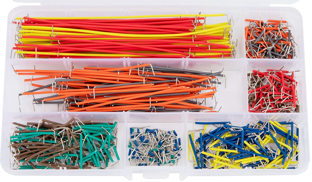
Choosing the appropriate wire for connecting between rows is crucial for successful breadboard prototyping. It is recommended to use single-core wires that retain their shape when bent. It is also important to select the appropriate wire size: if the wire is too large, it can damage the breadboard, while a wire that is too small can lead to unstable connections. To make your life easier, there are pre-formed jumper cable kits that can be easily found on Amazon and other retailers.
Alternatively, you can trim the cables to the appropriate length using wire cutters. Next, strip their ends with wire strippers, or use small scissors if you possess the necessary skills. Lastly, straighten and form the cable into the desired shape using flat-nose pliers. With these tools, you can quickly and easily create custom jumper cables that are tailored to your specific breadboarding needs.
Use middle nodes
If a node has too many components, it may be necessary to move some of the connections to another row and connect both rows together using a jumper wire. When creating these connections, it is important to avoid using long-flying wires like DuPont wires, as they can create more opportunities for mistakes or signal interference. Instead, it is recommended to use short jumper wires that are custom-cut to the appropriate length. This will help to minimize signal distortion and ensure that your circuit is functioning properly.
Plan on paper
If your circuit is complicated, it is a good idea to plan the connections on paper before you start cutting components to the right size and spend time assembling the circuit. Often, people find out that the routing is entirely wrong only after they have spent a lot of time putting it together. According to Murphy’s Law, one of your component leads will be cut too short, and you will not have a replacement on your desk. So, to avoid any trouble, map it out first!
Use short wiring
Keep wires short and tidy to avoid signal interference and messy circuit layouts.
Secure connections
Test each connection by gently wiggling the component to ensure it is secure. If you are using through-hole components such as a resistor, bend the leads with flat-nose pliers and cut them so that the component lays on the breadboard while the leads are in place. If you are unsure about the connection you can always use a multimeter to check for continuity.
Double-check connections
Before applying power to your circuit, it’s always a good idea to double-check your connections. It is easy to accidentally misplace a component and create unwanted connections or a short circuit. If everything looks fine but your circuit is still not working as expected after power-up, you can use a multimeter to check voltages at known nodes. This can help you to identify any potential issues with the circuit and ensure that everything is functioning properly.
If your circuit includes digital interfaces, you may want to use the logic analyzer feature of the ADALM2000 to check that the signals are as expected. This can help you to verify that your circuit is properly communicating and identify any potential issues with the digital signals.
Conclusions
In conclusion, breadboards are versatile tools that provide a quick and easy way to test and modify electronic circuits. Solderless breadboards, in particular, are popular due to their ease of use and reusability. While they are great for prototyping, it is important to keep in mind their limitations, such as the potential for mechanical instability and signal interference. By following some best practices and using appropriate tools such as wire cutters and multimeters, breadboards can be a powerful tool for any electronics enthusiast.
Thanks for this information. I’m looking to teach my 14 yr old what to do . Starting from knowing nothing.. any suggestions?
Hello Valerie thanks for commenting. I wrote you an email with a list of resources that you may want to consider. There is plenty on free resources out there.