
ChibiOS/HAL design: an object-oriented approach
The ChibiOS Hardware Abstraction Layer
The C programming language is clearly an imperative programming language not designed to be object-oriented. Anyway, the object-oriented approach remains something much more related to the design and mindset more than to syntax. The ChibiOS/HAL is an Hardware Abstraction Layer which design could be considered very object-oriented. We encountered it in almost every article related to ChibiOS but we often ignored its design as it comes with a series of demos which allow to use it easily without a deep knowledge of its internal mechanisms.
This article is dedicated to people who want to go in deep and see how stuff works. Starting from ChibiOS 3.0, ChibiOS/HAL became essentially a standalone product that is not rigidly attached to the OS and can be used on bare metal or in conjunction with any other RTOS.
ChibiOS/HAL provides a hardware abstraction allowing nevertheless a custom use of peripherals. HAL has undergone a lot of changes based on community’s suggestions and after years of upgrades and bug fixes, it has reached a high level of stability, reliability and flexibility.
To pursue its goals, HAL has:
- To encapsulate the driver complexities allowing somehow to properly address the hardware-dependent configuration: such implementation allows to cover many different scenarios.
- To provide an hardware-independent and universal high level API: this ensure that application are portable across different microcontrollers.
- To ensure an intrinsic optimization and provide and non-polled implementation to make HAL usable in Real Time applications.
- To be able to work as stand-alone in OS-less applications;
- To support most common peripherals like ADC, CAN, DAC, GPIO, ICU, PWM, SPI, TIM, UART, USB and many others.
Achieving abstraction using a layered architecture design
HAL is organized in a multi-layered way and more precisely it has two layers.
- The top layer which offers a universal Application Programming Interface (also abbreviated as API) we can directly approach.
- The low level driver (or LLD) layer which resolves differences across different hardware.
We could imagine this architecture as a LEGO wall: we can directly approach only from its top layer and this provide us an universal interface to the underlying low level. The interface remains unchanged in time and across different microcontrollers and this makes application built on top portable across different hardware and easy to maintain in time.
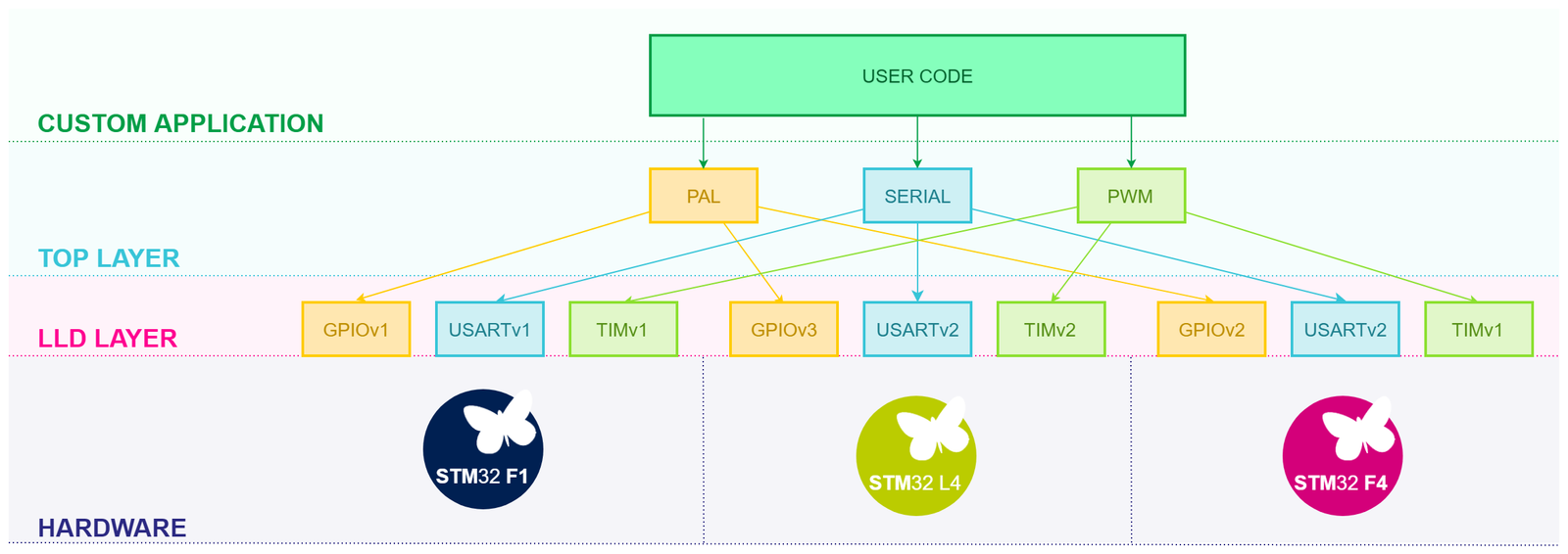
The trick is done linking proper LLD drivers depending on underlying microcontroller. To understand this let’s take a look to the organization of HAL files. HAL is contained inside the folder hal contained in our ChibiOS root directory.
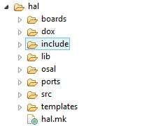
What we have called Top Layer is contained inside the two folders include and src. Exploring the first folder we will header files like hal_adc.h, hal_pal.h, hal_pwm.h, … while in the second source files like hal_adc.c, hal_pal.c, hal_pwm.c, … and so on.
Such code performs those operations which are common to any hardware. Operations which are hardware dependent are executed calling low level driver API. While there is only one top level layer there are many LLD layers which are related to specific platforms.
These LLD are contained inside the folder ports. As example considering the folder hal/ports/stm32/ we can find
- a folder for each STM32 subfamily which contains the low level drivers specific of that subfamily and the platform.mk (a piece of makefile used to list and link drivers used by that platform).
- a folder named LLD which contains certain driver which are common across more than a subfamily.
What follows is the platform.mk of the STM32F4xx subfamily were we can spot all the LLD used by it. As example F4 uses the ADCv2, CANv1, DACv1 and so on.
# Required platform files.
PLATFORMSRC := $(CHIBIOS)/os/hal/ports/common/ARMCMx/nvic.c \
               $(CHIBIOS)/os/hal/ports/STM32/STM32F4xx/stm32_isr.c \
               $(CHIBIOS)/os/hal/ports/STM32/STM32F4xx/hal_lld.c

# Required include directories.
PLATFORMINC := $(CHIBIOS)/os/hal/ports/common/ARMCMx \
               $(CHIBIOS)/os/hal/ports/STM32/STM32F4xx

# Optional platform files.
ifeq ($(USE_SMART_BUILD),yes)

# Configuration files directory
ifeq ($(CONFDIR),)
  CONFDIR = .
endif

HALCONF := $(strip $(shell cat $(CONFDIR)/halconf.h | egrep -e "\#define"))

else
endif

# Drivers compatible with the platform.
include $(CHIBIOS)/os/hal/ports/STM32/LLD/ADCv2/driver.mk
include $(CHIBIOS)/os/hal/ports/STM32/LLD/CANv1/driver.mk
include $(CHIBIOS)/os/hal/ports/STM32/LLD/DACv1/driver.mk
include $(CHIBIOS)/os/hal/ports/STM32/LLD/DMAv2/driver.mk
include $(CHIBIOS)/os/hal/ports/STM32/LLD/EXTIv1/driver.mk
include $(CHIBIOS)/os/hal/ports/STM32/LLD/GPIOv2/driver.mk
include $(CHIBIOS)/os/hal/ports/STM32/LLD/I2Cv1/driver.mk
include $(CHIBIOS)/os/hal/ports/STM32/LLD/MACv1/driver.mk
include $(CHIBIOS)/os/hal/ports/STM32/LLD/OTGv1/driver.mk
include $(CHIBIOS)/os/hal/ports/STM32/LLD/QUADSPIv1/driver.mk
include $(CHIBIOS)/os/hal/ports/STM32/LLD/RTCv2/driver.mk
include $(CHIBIOS)/os/hal/ports/STM32/LLD/SPIv1/driver.mk
include $(CHIBIOS)/os/hal/ports/STM32/LLD/SDIOv1/driver.mk
include $(CHIBIOS)/os/hal/ports/STM32/LLD/TIMv1/driver.mk
include $(CHIBIOS)/os/hal/ports/STM32/LLD/USARTv1/driver.mk
include $(CHIBIOS)/os/hal/ports/STM32/LLD/xWDGv1/driver.mk

# Shared variables
ALLCSRC += $(PLATFORMSRC)
ALLINC  += $(PLATFORMINC)
To complete the trick the proper platform.mk shall be included in the project makefile. As example the following codebox contains a snippet of makefile from a demo for the STM32 Nucleo-64 F401RE. We can see that it includes hal/ports/STM32/STM32F4xx/platform.mk
# Project, sources and paths
#

# Define project name here
PROJECT = ch

# Imported source files and paths
CHIBIOS = ../../..

# Licensing files.
include $(CHIBIOS)/os/license/license.mk
# Startup files.
include $(CHIBIOS)/os/common/startup/ARMCMx/compilers/GCC/mk/startup_stm32f4xx.mk
# HAL-OSAL files (optional).
include $(CHIBIOS)/os/hal/hal.mk
include $(CHIBIOS)/os/hal/ports/STM32/STM32F4xx/platform.mk
include $(CHIBIOS)/os/hal/boards/ST_NUCLEO64_F401RE/board.mk
include $(CHIBIOS)/os/hal/osal/rt/osal.mk
# RTOS files (optional).
include $(CHIBIOS)/os/rt/rt.mk
include $(CHIBIOS)/os/common/ports/ARMCMx/compilers/GCC/mk/port_v7m.mk
# Other files (optional).
include $(CHIBIOS)/test/lib/test.mk
include $(CHIBIOS)/test/rt/rt_test.mk
include $(CHIBIOS)/test/oslib/oslib_test.mk

# Define linker script file here
LDSCRIPT= $(STARTUPLD)/STM32F401xE.ld
To next table reports the LLD associated to each STM32 subfamily
| Sub-Family | ADC | BDMA | CAN | CRYP | DAC | DMA | EXTI | GPIO | I2C | MAC | OTG | QUADSPI | RTC | SDIO | SDMMC | SPI | TIM | USART | USB | xWDG |
| STM32F0 | ADCv1 | ND | CANv1 | ND | DACv1 | DMAv1 | EXTIv1 | GPIOv2 | I2Cv2 | ND | ND | ND | RTCv2 | ND | ND | SPIv2 | TIMv1 | USARTv2 | USBv1 | xWDGv1 |
|---|---|---|---|---|---|---|---|---|---|---|---|---|---|---|---|---|---|---|---|---|
| STM32F1 | Specific | ND | CANv1 | ND | DACv1 | DMAv1 | EXTIv1 | GPIOv1 | I2Cv1 | MACv1 | OTGv1 | ND | RTCv1 | SDIOv1 | ND | SPIv1 | TIMv1 | USARTv1 | USBv1 | xWDGv1 |
| STM32F2 | ADCv2 | ND | CANv1 | ND | DACv1 | DMAv2 | EXTIv1 | GPIOv2 | I2Cv1 | MACv1 | OTGv1 | QUADSPIv1 | RTCv2 | SDIOv1 | ND | SPIv1 | TIMv1 | USARTv1 | ND | xWDGv1 |
| STM32F3 |
ADCv3 Specific |
ND | CANv1 | ND | DACv1 | DMAv1 | EXTIv1 | GPIOv2 | I2Cv2 | ND | ND | ND | RTCv2 | ND | ND | SPIv2 | TIMv1 | USARTv2 | USBv1 | xWDGv1 |
| STM32F4 | ADCv2 | ND | CANv1 | ND | DACv1 | DMAv2 | EXTIv1 | GPIOv2 | I2Cv1 | MACv1 | OTGv1 | QUADSPIv1 | RTCv2 | SDIOv1 | ND | SPIv1 | TIMv1 | USARTv1 | ND | xWDGv1 |
| STM32F7 | ADCv2 | ND | CANv1 | CRYPv1 | DACv1 | DMAv2 | EXTIv1 | GPIOv2 | I2Cv2 | MACv1 | OTGv1 | QUADSPIv1 | RTCv2 | ND | SDMMCv1 | SPIv2 | TIMv1 | USARTv2 | ND | xWDGv1 |
| STM32H7 | ADCv4 | BDMAv1 | ND | CRYPv1 | ND | DMAv3 | ND | GPIOv2 | I2Cv3 | ND | ND | ND | RTCv2 | ND | ND | SPIv3 | TIMv1 | USARTv2 | ND | xWDGv1 |
| STM32L0 | ADCv1 | ND | CANv1 | ND | DACv1 | DMAv1 | EXTIv1 | GPIOv2 | I2Cv2 | ND | ND | ND | RTCv2 | ND | ND | SPIv1 | TIMv1 | USARTv2 | USBv1 | xWDGv1 |
| STM32L1 | Specific | ND | ND | ND | DACv1 | DMAv1 | EXTIv1 | GPIOv2 | I2Cv1 | ND | ND | ND | RTCv2 | ND | ND | SPIv1 | TIMv1 | USARTv1 | USBv1 | xWDGv1 |
| STM32L4 | ADCv3 | ND | CANv1 | ND | DACv1 | DMAv1 | EXTIv1 | GPIOv3 | I2Cv2 | ND | OTGv1 | QUADSPIv1 | RTCv2 | ND | SDMMCv1 | SPIv2 | TIMv1 | USARTv2 | USBv1 | xWDGv1 |
Driver enabling and peripheral allocation
HAL allows to completely exclude code from the compiled binary through the driver switch. Working with embedded systems, it is extremely usual to deal with textual configuration headers which contains a lot of preprocessor directives. A driverswitch is just a boolean constant definition which include/exclude piece of code from the compilation process. In ChibiOS the driver switches related are contained in the halconf.h file
The following code snippet has been taken by a demo for STM32 and we can see it contains two switches: the first one is enabled and includes all the code related to Serial Driver, the second one is disabled and excludes all the code related to PWM Driver.
/**
 * @brief   Enables the SERIAL subsystem.
 */
#if !defined(HAL_USE_SERIAL) || defined(__DOXYGEN__)
#define HAL_USE_SERIAL              TRUE
#endif

/**
 * @brief   Enables the PWM subsystem.
 */
#if !defined(HAL_USE_PWM) || defined(__DOXYGEN__)
#define HAL_USE_PWM                 FALSE
#endif
A driver relies on hardware peripheral. To use it we have then to assign a peripheral to the driver and this can be done acting on mcuconf.h.
As example in the following code we are assigning USART2 to the Serial Driver. As side note this code has been copied from the MCU configuration header of the original demo for STM32 Nucleo-64 F401RE.
/*
 * SERIAL driver system settings.
 */
#define STM32_SERIAL_USE_USART1             FALSE
#define STM32_SERIAL_USE_USART2             TRUE
#define STM32_SERIAL_USE_USART6             FALSE
#define STM32_SERIAL_USART1_PRIORITY        12
#define STM32_SERIAL_USART2_PRIORITY        12
#define STM32_SERIAL_USART6_PRIORITY        12
Note that is not possible to assign the same peripheral to different driver because this would generate conflict on IRQ management and the project would not compile.
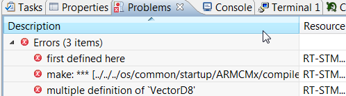
As instance, it is not possible to assign USART 2 both to the Serial Driver and UART Driver and trying to do will result in a compile error. In figure 4 the problem windows reports the compile error derived by such operation. The error is due to the tentative to assign the same IRQ line (VectorD8) to two different drivers.
Each ChibiOS driver can be enabled or disabled in the halconf.h file and each project has is own HAL configuration header. In the original demos all unused drivers are usually disabled. If you have launched the default demo you should have noticed that we use Serial Driver to print test suite results, and us most likely your project will be a copy of the default one most-likely you will find the SD already enabled.
/**
 * @brief   Enables the SERIAL subsystem.
 */
#if !defined(HAL_USE_SERIAL) || defined(__DOXYGEN__)
#define HAL_USE_SERIAL                      TRUE
#endif
The driver object
Each driver is represented by a structure and every API associated to a certain driver requires its pointer. As this structure contains almost every information related to driver, API doesn’t require a long list of parameters and moreover this implementation allows multiple instances.
As example considering the SPI driver we have an instance for each SPI peripheral
#if STM32_SPI_USE_SPI1 && !defined(__DOXYGEN__)
extern SPIDriver SPID1;
#endif

#if STM32_SPI_USE_SPI2 && !defined(__DOXYGEN__)
extern SPIDriver SPID2;
#endif

#if STM32_SPI_USE_SPI3 && !defined(__DOXYGEN__)
extern SPIDriver SPID3;
#endif
As example assigning the STM32 SPI1 to serial driver the SPID1 object would become available. Note that, the driver implementation inumbering is aligned to peripheral numbering: SPI peripheral 1 is associated to SPID1, SPI peripheral 2 is associated to SPID2 and so on.
We can also note that there is a certain strictness in coding style. We can indeed notice that
Each API of the a driver starts with the prefix. Function names are camel-case, preprocessor constants uppercase and variables lowercase.
Driver finite state machine
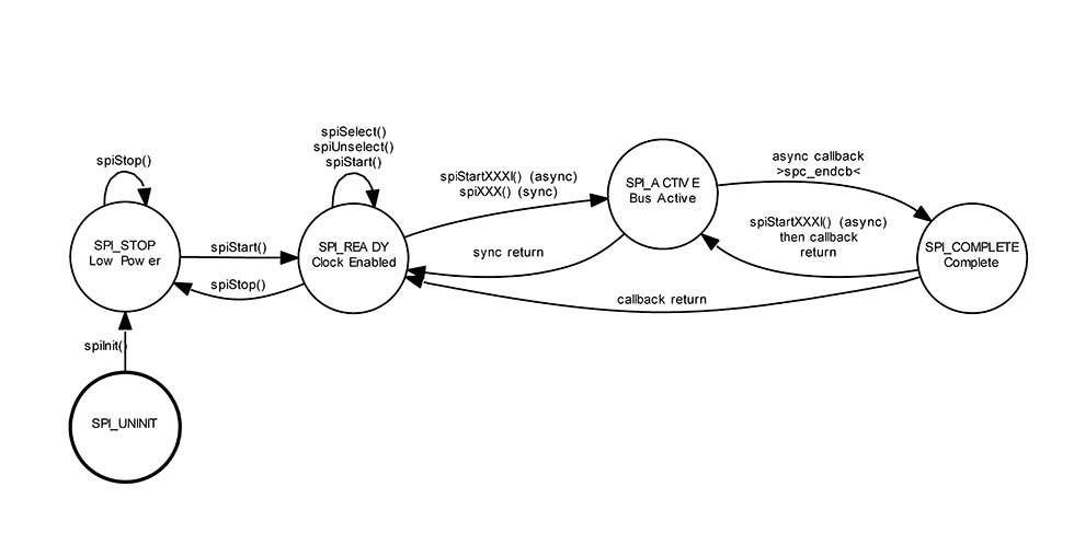
Each driver in ChibiOS\HAL implements a Finite State Machine. The current state of the driver is stored inside the object in a field named state (you can access it using structure syntax as example SPID2.state or PWMD1.state). The following image has been grabbed from the ChibiOS\HAL documentation and illustrates the finite state machine of the SPI driver
Driver initialization
Looking at SPI finite state machine, we cannot call function spiStart() on SPID1 if this driver is into the state SPI_UNINIT.
Every driver must be initialized and its state moved to XXX_STOP (in our example SPI_STOP): this operation is performed by a function named xxxInit() (in our example spiInit). There is an “init” function for every driver and they are called automatically by halInit() if the driver switch is enabled
/**
 * @brief   HAL initialization.
 * @details This function invokes the low level initialization code then
 *          initializes all the drivers enabled in the HAL. Finally the
 *          board-specific initialization is performed by invoking
 *          @p boardInit() (usually defined in @p board.c).
 *
 * @init
 */
void halInit(void) {
  /* Initializes the OS Abstraction Layer.*/
  osalInit();
  /* Platform low level initializations.*/
  hal_lld_init();
#if (HAL_USE_PAL == TRUE) || defined(__DOXYGEN__)
  palInit(&pal_default_config);
#endif
#if (HAL_USE_ADC == TRUE) || defined(__DOXYGEN__)
  adcInit();
#endif
#if (HAL_USE_CAN == TRUE) || defined(__DOXYGEN__)
  canInit();
#endif
#if (HAL_USE_DAC == TRUE) || defined(__DOXYGEN__)
  dacInit();
#endif
#if (HAL_USE_EXT == TRUE) || defined(__DOXYGEN__)
  extInit();
#endif
#if (HAL_USE_GPT == TRUE) || defined(__DOXYGEN__)
  gptInit();
#endif
#if (HAL_USE_I2C == TRUE) || defined(__DOXYGEN__)
  i2cInit();
#endif
#if (HAL_USE_I2S == TRUE) || defined(__DOXYGEN__)
  i2sInit();
#endif
#if (HAL_USE_ICU == TRUE) || defined(__DOXYGEN__)
  icuInit();
#endif
#if (HAL_USE_MAC == TRUE) || defined(__DOXYGEN__)
  macInit();
#endif
#if (HAL_USE_PWM == TRUE) || defined(__DOXYGEN__)
  pwmInit();
#endif
#if (HAL_USE_SERIAL == TRUE) || defined(__DOXYGEN__)
  sdInit();
#endif
#if (HAL_USE_SDC == TRUE) || defined(__DOXYGEN__)
  sdcInit();
#endif
#if (HAL_USE_SPI == TRUE) || defined(__DOXYGEN__)
  spiInit();
#endif
#if (HAL_USE_UART == TRUE) || defined(__DOXYGEN__)
  uartInit();
#endif
#if (HAL_USE_USB == TRUE) || defined(__DOXYGEN__)
  usbInit();
#endif
#if (HAL_USE_MMC_SPI == TRUE) || defined(__DOXYGEN__)
  mmcInit();
#endif
#if (HAL_USE_SERIAL_USB == TRUE) || defined(__DOXYGEN__)
  sduInit();
#endif
#if (HAL_USE_RTC == TRUE) || defined(__DOXYGEN__)
  rtcInit();
#endif
  /* Community driver overlay initialization.*/
#if defined(HAL_USE_COMMUNITY) || defined(__DOXYGEN__)
#if (HAL_USE_COMMUNITY == TRUE) || defined(__DOXYGEN__)
  halCommunityInit();
#endif
#endif
  /* Board specific initialization.*/
  boardInit();
/*
 *  The ST driver is a special case, it is only initialized if the OSAL is
 *  configured to require it.
 */
#if OSAL_ST_MODE != OSAL_ST_MODE_NONE
  stInit();
#endif
}
If a ChibiOS driver is enabled in the HAL configuration file, it is automatically initialized on HAL initialization. Initialization is related to variable initialization more than on hardware configuration.
Configuring a driver
Before to use it, the a driver shall be properly initialized and configured. This operation is carried out by another function: the start. The following code box reports some start function from different drivers.
/**
 * @brief   Configures and starts the driver.
 *
 * @param[in] sdp       pointer to a @p SerialDriver object
 * @param[in] config    the architecture-dependent serial driver configuration.
 *                      If this parameter is set to @p NULL then a default
 *                      configuration is used.
 *
 * @api
 */
void sdStart(SerialDriver *sdp, const SerialConfig *config) {
  ...
}


/**
 * @brief   Configures and activates the SPI peripheral.
 *
 * @param[in] spip      pointer to the @p SPIDriver object
 * @param[in] config    pointer to the @p SPIConfig object
 *
 * @api
 */
void spiStart(SPIDriver *spip, const SPIConfig *config) {
  ...
}


/**
 * @brief   Configures and activates the ADC peripheral.
 *
 * @param[in] adcp      pointer to the @p ADCDriver object
 * @param[in] config    pointer to the @p ADCConfig object. Depending on
 *                      the implementation the value can be @p NULL.
 *
 * @api
 */
void adcStart(ADCDriver *adcp, const ADCConfig *config) {
  ...
}
Such functions shall be called at least once by the user application before the real usage. Their purpose is to configure the peripherals and this involves setup of all that hardware configurability.
In ChibiOS/HAL every driver except PAL shall be started before to be used.
The xxxStart function receives two parameters which are a pointer to the serial driver object we want to start (e.g. &SD1, &SPI3, &PWM7 or whatever is the driver we are going to use) and a pointer to a structure which represent the related configuration. This structure contains all the dependencies which are strictly related to the underlying hardware. This means that moving from a STM32 family to another which has a different underlying hardware we most likely have to apply some changes to these configuration structures.
Starting a driver we need a pointer to it and a pointer to its configuration structure. This structure contains all the HW dependencies and has to been reviewed if we port our application on a different microcontroller.
The start function usually enables peripheral clock. In certain application (especially those addressed to low power) it is undesidered to keep a peripheral clocked when it is not used. Because of that there is another function we could use to stop the driver and stop the peripheral clock: the stop.
/**
 * @brief   Stops the driver.
 * @details Any thread waiting on the driver's queues will be awakened with
 *          the message @p MSG_RESET.
 *
 * @param[in] sdp       pointer to a @p SerialDriver object
 *
 * @api
 */
void sdStop(SerialDriver *sdp) {
  ...
}


/**
 * @brief   Deactivates the SPI peripheral.
 * @note    Deactivating the peripheral also enforces a release of the slave
 *          select line.
 *
 * @param[in] spip      pointer to the @p SPIDriver object
 *
 * @api
 */
void spiStop(SPIDriver *spip) {
  ...
}


/**
 * @brief   Deactivates the ADC peripheral.
 *
 * @param[in] adcp      pointer to the @p ADCDriver object
 *
 * @api
 */
void adcStop(ADCDriver *adcp) {
  ...
}
This function can be called by the user application when the peripheral is unnecessary. It is almost intuitive that after a stop we need a new start to be able to use again the driver.
Start Do Stop
A most common paradigm is the Start-Do-Stop:
- we start the driver when needed configuring it.
- we do some operations on that driver.
- we stop it as soon as it has completed operations.
/* Starting Serial Driver 2 with my configuration. */
sdStart(&SD2, &my_sd_configuration);

/* Doing some operation on Serial Driver 2. */

/* Stopping. */
sdStop(&SD2);

...

/* Starting again. */
sdStart(&SD2, &my_sd_configuration);

/* Carrying out other operation. */

/* Stopping. */
sdStop(&SD2);
This offers advantage especially if peripheral is actually used in a small slice of the whole time amount of execution time.
It is possible to stop a driver to reduce hardware power consumption when peripheral is used for a small percentage of execution time. After being stopped a the driver shall be re-started to be used again.
Changing configuration on the fly
An approach similar to Start-Do-Stop can be used is used when we need to change driver configuration on-the-fly. In such scenario we can start peripheral multiple time with different configuration. Note that stop is not required rather is discouraged as in case of subsequent start operation certain operation are skipped.
/* Starting Serial Driver 2 with my configuration. */
sdStart(&SD2, &sd_cfg1);

/* Doing some operation on Serial Driver 2 with configuration 1. */
sdDoStuff(&SD2, additional_params);

/* Starting again. */
sdStart(&SD2, &sd_cfg2);

/* Doing some operation on Serial Driver 2 with configuration 2. */
sdDoStuff(&SD2, additional_params);
It is possible to start driver more than once with different configuration in case we need to change driver configuration on-the-fly.
The configuration structure is composed by two separated parts: the first part remains unchanged across all kind of hardware, the second is strictly hardware dependent. Dealing with configuration there are some hints that can help you to figure out how to correctly compose them:
- Take a look to demos under the testhal folder and testex folders: in these demos you can find some precomposed configuration that you can copy and use in your application. As the configuration depends on hardware be sure to pick a demo for the subfamily you are currently using.
- You can take a look to the definition of configuration structure following the breadcrumbs: first you need to detect which LLD your platform is using through the platform.mk file, then you have to open the related low level driver header where you can find the configuration structure definition.
- Those fields which are related to hardware are described in the reference manual, use it to spot the meaning of each bit.
- Remember that the start function usually does some internal obvious modification to register values passed through the configuration.
- There are some simple techniques to change certain bit of the register leaving others unchanged. Such operation takes the name of bit-masking and the adopted paradigm to deal with registers read-modify-write. This is a knowledge you really should do have. If don’t I highly suggest to read this article (even at later moment).
- You do not have to define register bitmasks as they are already defined and available in CMSIS header files. You can find these files under the folder chibios182\os\common\ext\ST.
Be the first to reply at ChibiOS/HAL design: an object-oriented approach