
A complete overview of LEDs: from theory to applications
Introduction
When it comes to lighting, LEDs have become increasingly popular in recent years due to their numerous advantages over traditional light sources such as incandescent bulbs and fluorescent tubes. One of the most significant advantages of LEDs is their energy efficiency. Unlike incandescent bulbs, which waste a lot of energy as heat, LEDs convert a higher percentage of the energy they consume into visible light. Additionally, LEDs are more durable and long-lasting than incandescent bulbs, and they can be manufactured in a range of colors without the need for color filters or additional components, making them ideal for use in displays and lighting applications. Finally, LEDs can be easily dimmed or controlled using electronic circuits, making them highly versatile in a wide range of applications.
In this article, we will provide a comprehensive introduction to the theory of LEDs, including how they work, their model, the equation for calculating the required series resistor, thermal run, RGB LEDs, and current hogging. We will also explain why dimming is essential and how to do it effectively. This article is intended to be the foundation for the upcoming hands-on exercises that demonstrate how to hook up LEDs to a microcontroller and generate precise digital waveforms using the ChibiOS drivers.
The Lighting emitting diode
Definition and working principle
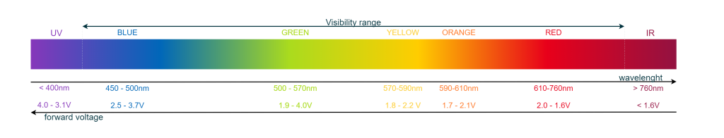
LEDs, or Light Emitting Diodes, are semiconductor devices that convert electrical energy directly into light energy. The LED’s light-emitting properties are a result of a process called electron-hole recombination. When a forward voltage is applied to an LED, it causes current to flow through the LED in the forward direction. This causes electrons and holes to move towards each other and eventually recombine at the junction between the P-type and N-type semiconductors that make up the LED. When the electrons and holes recombine, energy is released in the form of photons if the material has a direct bandgap. The energy of the emitted photons corresponds to the bandgap of the material used to build the LED, which determines the wavelength and color of the associated radiation. In other words, the color of the LED is fixed by the material it is made from, and it cannot be changed by adjusting the current or voltage applied to it. The energy gap of the material also influences the voltage required to turn on the LED, which will be discussed in more detail later in this article.
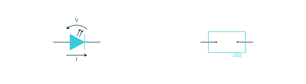
Polarity
Like other diodes, LEDs have polarity, which means that current can flow through them only in a specific direction. For this reason, the two pins of the LED have different names and are marked to indicate their polarity.
The anode is the pin through which current flows into the LED, and it is typically marked as the positive lead. The cathode is the pin through which current flows out of the LED, and it is typically marked as the negative lead. In other words, to ensure the proper polarity, we want to connect the positive voltage to the anode and the negative voltage to the cathode.

When it comes to through-hole components, the anode is typically the longer lead. With SMD LEDs, it is common to find a green mark on one side of the component to indicate the cathode. However, this is not always the case, so it is essential to refer to the datasheet of the component to determine the polarity of the LED.
Using a multimeter to detect the polarity
If you are unsure about the polarity of an LED, you can use the diode test function on a multimeter to verify its polarity. This function allows you to test the forward voltage across a diode and determine its polarity. To use the diode test function:
- Turn off power to the circuit and set the multimeter to the diode test mode, which is typically indicated by a diode symbol on the dial.
- Touch the black probe to the cathode of the LED (the shorter lead) and the red probe to the anode (the longer lead).
- If the LED’s polarity is correct, the multimeter will display a voltage reading that represents the forward voltage of the diode. If the multimeter provides enough current, you may also see the LED turning on.
- If the voltage indication stays at 0, it’s likely that you have the wrong polarity, and you need to reverse the probes. If both polarity combinations result in a voltage of 0, it could indicate that the LED is damaged and may need to be replaced.

Performing a diode test with a multimeter is a useful way to verify the polarity of an LED before hooking it up to a circuit, as well as to test other semiconductor devices like diodes or transistors.
From the I-V equation to the simplified models
The I-V equation of an LED
The I-V (current-voltage) equation of an LED describes the relationship between the current flowing through an LED and the voltage applied across it. This equation is important because it allows us to understand the behavior of the LED under different operating conditions and to design circuits that use the LED effectively.
The equation is based on the physics of semiconductor materials and is in the same form as that of a normal diode but with different parameters:
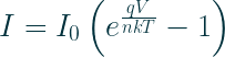
In this equation,
- I is the current flowing through the LED,
- V is the voltage applied across the LED,
- I0 is a constant known as the reverse saturation current,
- q is the elementary charge of an electron
- k is Boltzmann’s constant
- T is the temperature in Kelvin
- n is the emission coefficient of the LED material.
Considering that the thermal voltage can be expressed as

we can rewrite the formula as

The Thermal Voltage is a fundamental property of conductors that arises due to the random motion of electrons in the material. It is a voltage that exists even in the absence of any applied voltage, and it is proportional to the temperature. The thermal voltage is an important consideration in the design of electronic circuits, particularly in low-noise applications, as it contributes to the overall noise floor of the system. At room temperature (300 K), the thermal voltage (kT/q) is approximately 25.85 millivolts (mV).
Considerations on the equation
Let us take a closer look at the equation that describes the behavior of an LED and plot it to better understand how it works
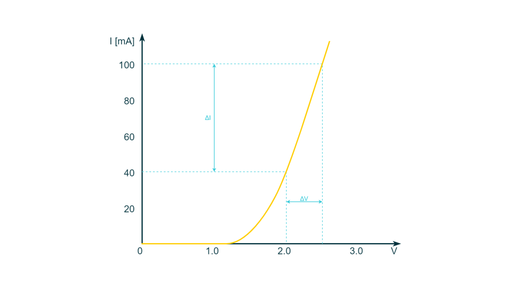
To understand this equation, we can look at it from two perspectives. First, if we provide a forward voltage to the diode, a current will flow through it. Alternatively, if we push a current through the LED, a voltage drop will occur at its pins. In both cases, the current and voltage of the LED can be seen as the input and output of the system.
The shape of the current-voltage curve depends on various factors, including the material and geometry of the LED, which influence the values of I0 and n. The temperature of the material also plays a crucial role in determining the curve’s shape, as it affects the value of VT.
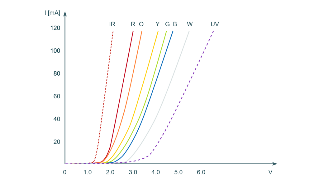
The main issue with LEDs is that their actual characteristics can vary significantly, even among LEDs from the same production batch. Consequently, it can be challenging to find datasheets that describe the device thoroughly. This difference is particularly evident when we compare the curves of LEDs of different colors.
Some specific LED parts used for lighting purposes come however with more comprehensive data sheets at a higher cost per part. The reason for this cost increase is that the LEDs must be characterized individually and then sorted to fit specific parameters with given tolerances. However, it also adds to the overall cost of production, which is reflected in the final price.
The nonlinearity of the LED’s I-V equation poses another challenge, as it does not mix well with the methods of circuit analysis. To mathematically define the behavior of LEDs effectively in circuit analysis, models are needed. These models provide an approximation of the LED’s I-V characteristics and, by using them, engineers can ensure that their circuits operate as intended and that the LED’s unique properties are fully utilized.
Characterizing an LED
To characterize an LED, the part must be treated as a single-input, single-output system. This means that the process involves applying a current through the LED and measuring the resulting voltage drop. This operation is performed for various current inputs to build the I-V characteristics.
Current is used as the input and voltage as the output in this process for a specific reason.
Let us examine this further by calculating the output voltage when we apply a known current and the output voltage when we apply a current that is 10 times greater and examining the difference. If we apply the two currents and neglect the negative term, which does not contribute significantly in forward polarization, we have:


if we take the ratio between the two equations we get
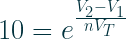
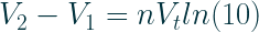
For n = 1 at room temperature, the change in voltage will be approximately 60mV. In other words, if we used the voltage as an input to the system, a change of 60mV would cause a one-order-of-magnitude change in the current, making it very difficult for us to accurately characterize the part.
LED models
To use the LED in circuit analysis, we need to create models that fit the theory. When the LED is reversely polarized, the exponential term in the I-V equation approaches 0, and the resulting current that flows through the LED becomes:

This current is very small and can be neglected. Therefore, the model of the LED in reverse polarization is simply an open circuit.
In forward polarization, the current is very small until a certain voltage is reached. From that point, the current increases almost linearly with the voltage. This is why the typical model chosen for LEDs is a battery in series with a resistor. The battery is placed in the opposite polarity to the main generator to indicate the passive behavior of the part, and its voltage indicates the forward voltage of the diode itself. The series resistor provides the extra slope to the curve
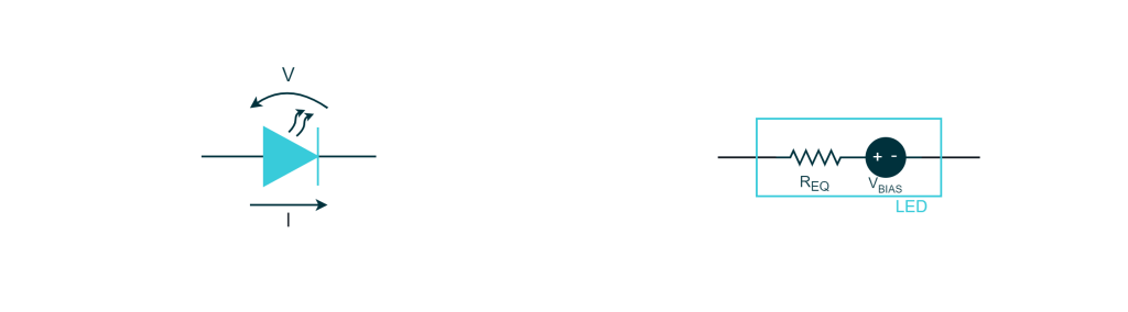
It is possible to determine the values of the LED forward voltage and the series resistor graphically. If we have the I-V characteristic of the LED, we can draw a line that coincides with the rising portion of the exponential curve and extend the line to the voltage axis. The slope of this line is equal to the inverse of the series resistance, and the intercept with the voltage axis represents the forward voltage of the LED when the current is zero.
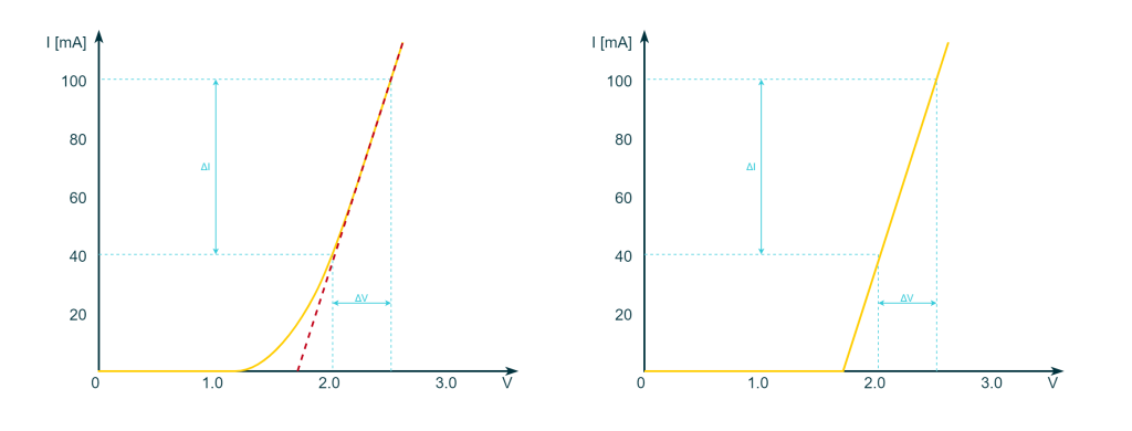
For example, in the previous figure, VBIAS is something like 1.8V a REQ is (2.5 – 2.0) \(0.1 – 0.04) that is 8.333Ω.
It is important to note that the inaccuracy of the forward polarization model is more visible at VBIAS, where the step function is farther away from the knee of the exponential curve.
The thermal run and the need for an external resistor
The behavior of the LED equation is strongly influenced by temperature, as shown in the graph below. At a fixed voltage, higher temperatures lead to higher currents.
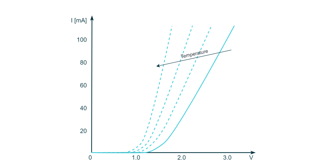
This can be explained by the fact that higher temperatures increase the thermal agitation, which creates more electron-hole pairs that drift away due to the potential across the material, thus increasing the current.
While the dependence on temperature would not be an issue if we were driving the LED with a constant current, the reality is that it is easier to create a controlled voltage generator than a current generator. As a result, most LEDs are driven with a constant voltage, which creates a serious problem known as thermal run that, if not controlled, can cause the LED to break.
When a specific voltage is applied to the diode, there is a corresponding current flow in line with the I-V characteristic and the temperature of the part. The current flow causes electrons to move across the material and transfer part of their kinetic energy to the material by impact. This energy causes the material to vibrate around its center of equilibrium, which is known as thermal agitation or heat. In other words, the current flow increases the temperature of the material, which in turn increases the current, generating a cycle of increasing temperature and current. This cycle is what we call a thermal run, and if the material is not cooled down in time or if the current is not controlled, it can lead to a current too high for the material to sustain and ultimately result in permanent damage to the LED.
The easiest way to control the thermal run is by placing a resistor in series with the LED. The resistor will limit the current if it arises and break the cycle. to understand this better let us consider the following circuit
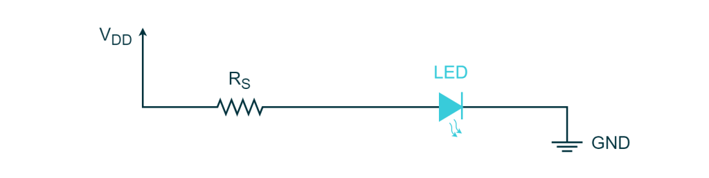
If we apply Kirchhoff Voltage law we can notice that the total voltage of the generator is split between the LED and the series resistor

If the heat would cause an increase in the current, according to Ohm’s law the voltage drop on the resistor will increase as well. The higher voltage drop on the resistor will reduce the voltage drop across the LED. This ultimately will reduce the current of the LED breaking the cycle. We can conclude that the resistor introduces a compensation that can limit current in case of thermal drift.
The choice of the external series resistor
The series resistor has a direct impact on the LED current and therefore the intensity of light emitted. Choosing the appropriate resistor size is a common challenge when working with LEDs. The selection process depends on factors such as the color of the LED and the main voltage value. To properly choose the resistor size, we need to refer back to the LED model.
Let us consider the previous circuit and replace the LED with the previously described model.
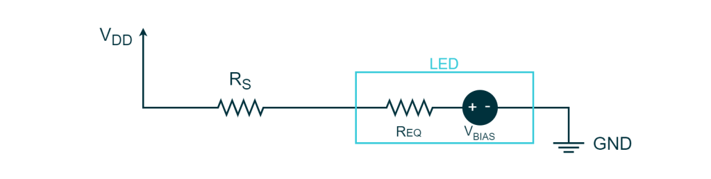
Using the Kirchhoff Voltage Law on this circuit we have


And considering all the parameters except for the external series resistance we can rewrite it as

At this point, choosing the appropriate resistor value for a desired current given the generator voltage and the parameters of the LED is a straightforward calculation.
The following table provides the values of the series resistance for different colors of LEDs and some plausible values of the forward voltage and the internal series resistance of the LED. In this specific case, the desired current has been fixed to a typical value of 10 mA. Note that depending on the material used to build the LED the voltage can change a lot. If you need precise current flow, once again you may want to characterize the LED and choose the proper resistor.
| Color | VBIAS [V] | REQ [Ω] | RS @10mA (VDD = 3.3V) [Ω] | RS @10mA (VDD = 5.0V) [Ω] |
| Infrared | 1.0 | 7.5 | 222.5 | 392.5 |
|---|---|---|---|---|
| Red | 1.6 | 10.0 | 160 | 330 |
| Orange | 1.7 | 11.7 | 148.3 | 318.3 |
| Yellow | 2.0 | 13.3 | 116.7 | 286.7 |
| Green | 2.1 | 16.7 | 103.3 | 273.3 |
| Blue | 2.3 | 16.7 | 83.3 | 253.3 |
| White | 2.5 | 21.7 | 58.3 | 228.3 |
| UV | 3.3 | 21.7 | impossible | 148.3 |
To calculate these values we have made a spreadsheet that can be used to recalculate these values depending on the current
LED Resistance computation
Current hogging
One common issue with LEDs is current hogging. Looking at the I-V curve of an LED, we can see that the impedance offered by the LED is the inverse of the slope of the curve. We can notice that the internal series resistance of the LED is very high until it turns on, and then its value drops to a few ohms.
This presents a particular problem when connecting LEDs in parallel. Consider the following circuit:
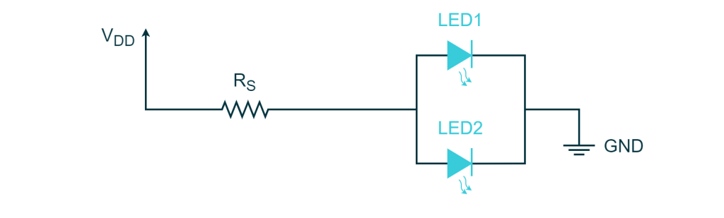
The problem with the circuit in question is that one of the two LEDs may have a lower forward voltage than the other. As a result, when the generator is turned on, the LED with the lower forward voltage will offer a lower resistance path for the current to flow through, causing most of the current to flow through this LED. This will cause the LED to begin turning on, reducing its equivalent series resistance and causing it to hog the current. Ultimately, only the LED with the lower forward voltage will turn on.
To avoid this problem, a separate resistor should be used for each branch, effectively preventing the connection of LEDs in parallel.
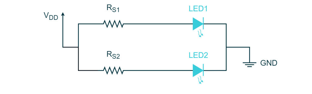
In this case, even when the first LED is turned completely on, the series resistor limits the current on that branch allowing some current to flow into the other branch that will turn on the second LED.
RGB LEDs
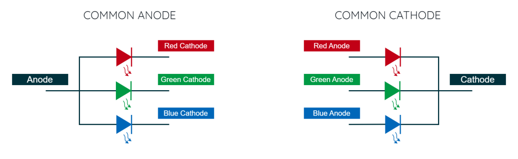
An RGB LED is a type of LED that contains three separate LEDs within a single package, one red, one green, and one blue. By controlling the intensity of each of these LEDs, a wide range of colors can be generated.
There are two types of RGB LED: common anode and common cathode. In a common cathode RGB LED, the cathodes of all three LEDs are connected together and the anodes are separate. Conversely, in a common anode RGB LED, the anodes of all three LEDs are connected together and the cathodes are separate.
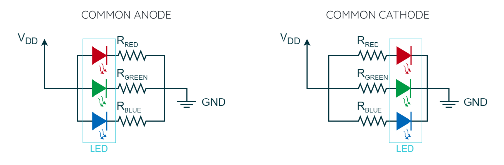
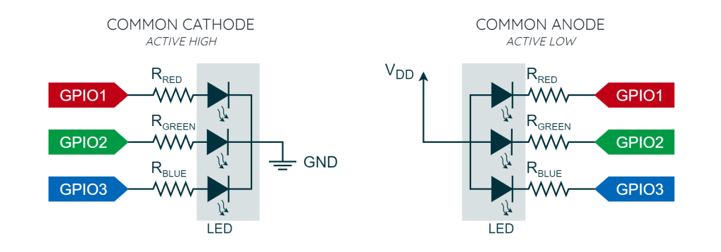
The problem of current hogging is more evident with RGB LEDs since each diode has a different forward voltage and requires a separate series resistor. As a result, a single resistor cannot be connected to the common lead. The proper way to power up these LEDs is to have a separate series resistor per junction. Therefore, the circuit for an RGB LED with a series resistor would look like the following.
Driving LEDs with a Microcontroller
Up until now, we have shown LEDs to be always connected between VDD and the ground of a power supply, and therefore always on. However, our ultimate goal is to control them, which means turning them on and off with a specific frequency or even dimming their luminosity for applications such as lighting or color generation with an RGB LED.
When it comes to driving a single-junction LED, we can achieve it by replacing one of the two connections to VDD or ground with a GPIO configured as digital output
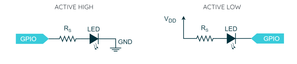
Depending on which side we connect the GPIO, we have two different configurations:
- Active High, where setting the GPIO to logical high turns on the LED and vice versa.
- Active Low, where setting the GPIO to logical low turns on the LED and vice versa.
For an RGB LED, the configuration is fixed by the type of LED in use. If we were to use a common cathode LED, the cathode will always be connected to the ground and the three anodes to three separate GPIOs via series resistors: this configuration is an Active High logic (i.e. set the GPIO to logic high to turn on the related junction). Conversely, a common anode LED requires the anode to be connected to VDD, and the branches to the GPIOs via resistors: this configuration is an Active Low logic.
Now, by turning on and off specific junctions we can obtain seven colors as shown in the following table
| Color | Red junction | Green junction | Blue junction |
|---|---|---|---|
| Red | ON | OFF | OFF |
| Green | OFF | ON | OFF |
| Blue | OFF | OFF | ON |
| Orange | ON | ON | OFF |
| Azure | OFF | ON | ON |
| Purple | ON | OFF | ON |
| White | ON | ON | ON |
LED dimming
As previously mentioned, changing the current in an LED can slightly alter its color. Furthermore, the light emitted by an LED is actually proportional to its current. Hence, dimming an LED while maintaining its color accuracy looks like an impossible task. In reality, it is possible by rapidly turning the LED on and off at a frequency too high for the human eye to detect.
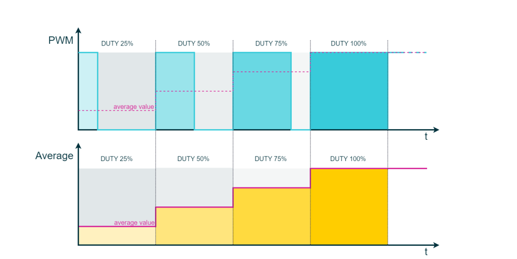
In this technique, the LED is powered by a square wave with a fixed frequency and logical high and low levels. The duty cycle of this square wave is adjusted to vary the percentage of time that the LED is on versus off. This changes the amount of power delivered to the LED, the number of photons generated per period, and ultimately the perceived brightness of the LED. This technique takes advantage of the persistence of vision, which allows the human eye to perceive the LED as continuously emitting light even though it is rapidly turning on and off.
Indeed, the human eye functions as a low-pass filter, typically with a cutoff frequency ranging from 50 to 90 Hz. Consequently, if an LED blinks at a frequency above 90 Hz, it becomes imperceptible to the human eye. The “biological” low-pass filter smooths the waveform, and the resulting brightness is proportional to the signal’s average, which is essentially related to the duty cycle.
A common and cost-effective way of generating square waves is by using a native peripherals of microcontrollers called Pulse Width Modulation (PWM). This digital modulation technique encodes information by varying the duty cycle of square waves. Although PWM has been replaced by more advanced communication techniques in some domains, it remains prevalent in control systems such as H-Bridges or LED dimming. Therefore, modern microcontrollers are still equipped with peripherals that can generate PWM signals.
In a separate article, we will explore the mathematical properties of square waves and provide a comprehensive guide on how to generate them using PWM peripherals.
For now, it is important to note that by leveraging the persistence of vision and the PWM signals, it is possible to dim the LED without causing any noticeable color shift. During the “on” time of the PWM, the LED is actually fully turned on with a fixed voltage and current. Having the LED blinking with the same color impress ensures that the color stays the same across the entire range of luminosity.
In reality, it should be noted that the current can still shift slightly due to temperature changes or noise in the PWM signal. In applications where color accuracy is critical, such as in OLED TVs or automotive lighting, dedicated programmable LED drivers are employed: these drivers generate PWM signals ensuring constant current against noise and temperature by continuously monitoring and controlling its outputs.
Conclusions
In conclusion, understanding the fundamental characteristics of LEDs is essential to working with them effectively. We have covered the basic theory of LED behavior, how to model them with battery and resistor circuits, and the issue of current hogging with RGB LEDs. Additionally, we have discussed the concept of LED dimming and how PWM can be used to achieve this effect. Armed with this knowledge, we can move on to practical exercises to build and control LED circuits.
Be the first to reply at A complete overview of LEDs: from theory to applications