
Detecting obstacle with IR Sensor and Arduino
Introduction
An object can be detected with an infrared system consisting of an infrared transmitter and a receiver. More in detail an IR transmitter, also known as IR LED, sends an infrared signal with a certain frequency compatible with an IR receiver which has the task to detect it. There are different kind of IR sensors for different type of application. IR technology is used, for example, in proximity sensors to detect a near object, in contrast sensors to find a path or in counting sensors to count objects.
Principle of operation
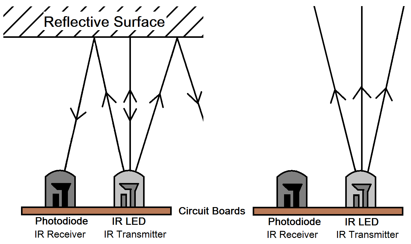
The IR transmitter sends an infrared signal that, in case of a reflecting surface (e.g. white color), bounces off in some directions including that of the IR receiver that captures the signal detecting the object.
When the surface is absorbent (e.g. black color) the IR signal isn’t reflected and the object cannot be detected by the sensor. This result would occur even if the object is absent.
IR transmitter and IR receiver
The IR transmitter is a particular LED that emits radiation in the frequency range of infrared, invisible to the naked eye. An infrared LED just works as a simple LED with a voltage of 3V DC and a current consumption of about 20mA. The IR receiver, such as a photodiode or a phototransistor, is capable of detect infrared radiation emitted from the IR transmitter. Aesthetically it is similar to a LED but the external capsule can be wrapped by a dark color film.
IR Sensor FC-51
The sensor used in our demo is model FC-51. It is a cheap sensor easily available on the internet for less than 2$ but unfortunately we didn’t find the datasheet. In any case we will explain the operation of the related electronic circuit and subsequently implement some demo to test its functioning.
Pinout and schematic

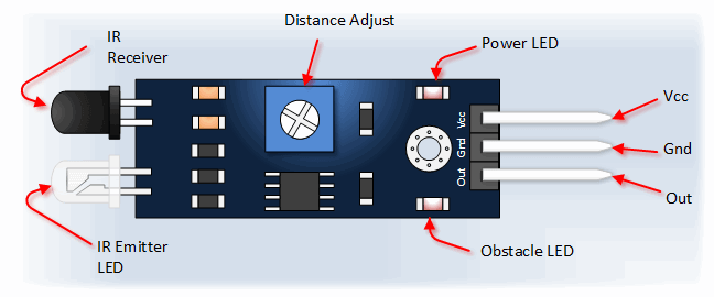
The package has three connection pins:
- Vcc to the power supply 3-5V DC;
- Gnd to the ground reference;
- Out for the digital output signal of the sensor.
This sensor detects objects at a distance in range between 2~30cm. With the potentiometer you can calibrate the sensitivity according to the application and environmental conditions (e.g. brightness). The IC LM393 is an open-collector voltage comparator which provides an output if there is a pull-up R between the output of the IC (DO) and the power supply Vcc (R=10KΩ). The output DO is:
- high if the object is not detected;
- low if the object is detected.
Proposed Demos explained
Test IR sensor FC-51 with serial terminal (Demo 01)
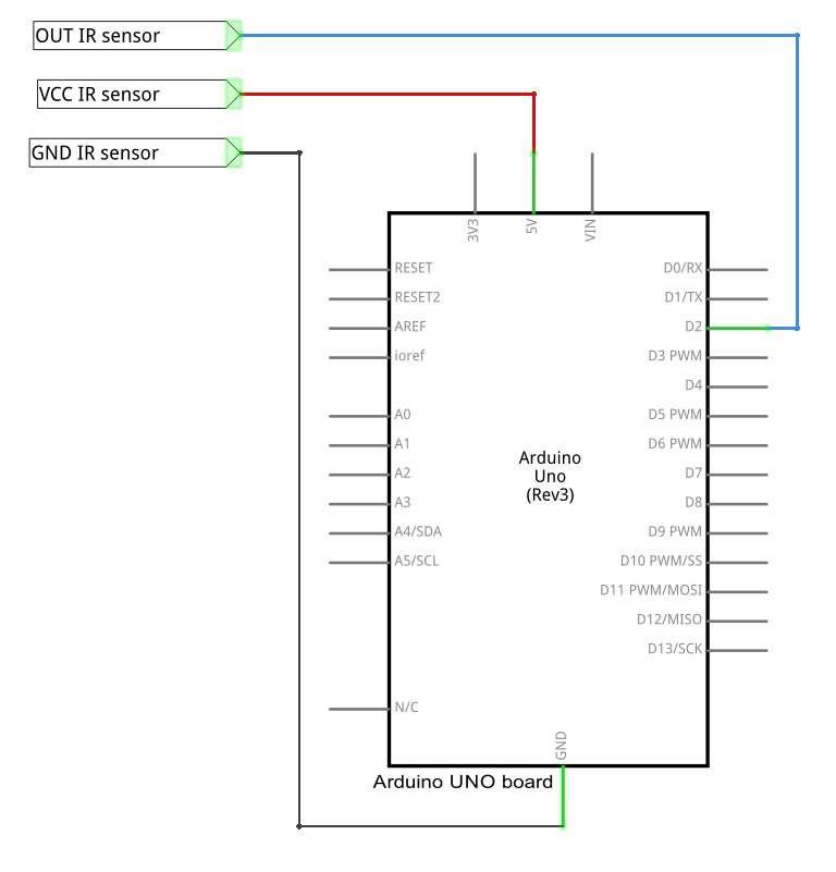
In the first demo, through the connection between the Arduino serial port and the PC, we will read about the detection of the object.
Lets take a look to steps required by this demo:
- We connect the OUT pin of the sensor to digital pin 2 of Arduino called IR.
- The setup() function is performed only once before the main loop. We insert here the initialization code which enables serial port Arduino and sets the digital pin 2 as input.
- loop() is the main function and is cyclically repeated until you turn off the Arduino board. We convert in C language the operation of the electronic circuit analyzed before. We save in the variable detection the value taken from the pin IR with the specific function digitalRead, if the value is low there is an object otherwise there isn’t.
Lets take a look to our code:
#define IR 2
int detection = HIGH;    // no obstacle
void setup() {
  Serial.begin(9600);
  pinMode(IR, INPUT);
}
void loop() {
  detection = digitalRead(IR);
  if(detection == LOW){
    Serial.print("There is an obstacle!\n");
  }
  else{
    Serial.print("No obstacle!\n");
  }
  delay(500);    // in ms
}
IR sensor FC-51 and LED (Demo 02)
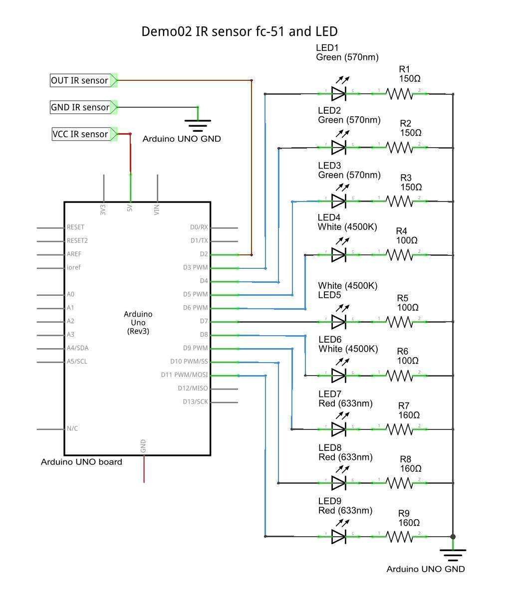
In this demo we associate an input to each operation state of IR sensor. The required components are:
- IR sensor FC-51;
- 3 x Green LEDs;
- 3 x R=150Ω;
- 3 x White LEDs;
- 3 x R=100Ω;
- 3 x Red LEDs;
- 3 x R=160Ω.
Remember that the I/O pins can absorb/disburse up to 40mA max, total maximum 200mA (see ATmega328P datasheet at page 313).
Lets take a look to steps required by this demo:
- We connect the OUT pin of the sensor to digital pin 2 of the Arduino. We define the digital pins of LEDs as an array of pins, from 3 to 11 called LedPIN.
- The setup() function is executed only once before the main loop. In addition to the initialization already seen, we call the 9 LED as output using a for loop.
- The loop() function is the main function and is cyclically repeated until you turn off the Arduino board. We save in the variable detection the value taken from pin IR with the specific function digitalRead(). This value can be low, if there is an object, or high if there is no object. We do this loop every millisecond.
Lets take a look to our code:
#define IR 2    // digital pin input for ir sensor
int detection = HIGH;    // no obstacle
int i = 0;
// array digital pin for: green led(3,4,5) - white led (6,7,8)- red led (9,10,11)
int LedPIN[] = {3, 4, 5, 6, 7, 8, 9, 10, 11};

void setup() {
  pinMode(IR, INPUT);
  for(i = 0; i < 9; i++){
    pinMode(LedPIN[i], OUTPUT);
  }
}
void loop() {
  detection = digitalRead(IR);
  if(detection == LOW){
    BlinkLED();
  }
  else{
    LedOFF();
  }
  delay(1);
}
Download for Arduino IDE
These demos have been tested under Arduino IDE 1.6.7:
Hi I just wanted to know how to detect like a train passing on a model railway and then initiate the boom gates using my IR obstacle sensor.
thanks
Hi, thanks for visiting us.
You can follow the principles explained in the demos of this article. You should look for a transiction of the variable
Detectionfrom LOW to HIGH or viceversa.I have used one of these sensor modules, but it appears that very different conditions in ambient for example, morning and night light, makes calibration a bit hard.
Have you experienced that?
Hello there. The module is quite simple and this is perfectly normal.
i just want to detect some particular color object using obstacle sensor.The color can be anything.Give me some idea…..Thank you
Hi,
you could use the obstacle detection joint with a color sensor like the TCS3200
How sensitive teh sensor. Can I use it to detect the water droplets?
I don’t think so, I guess the reflections will create some issue for this scenario.
The answer from Marco it´s true,
quite an important application for such a puny sensor module. dont wanna sound condescending, but the novice application shown is quite non-reflective of its real life applications,
apart from that, the module has been demoed well! GOOD JOB!