
Getting started with mikroe BUZZ Click using ChibiOS/HAL
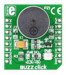
BUZZ Click
BUZZ Click is a click board with a mikroBus form factor. It is substantially composed of a piezoelectric speaker having a resonant frequency at 3.8 kHz: this means we should expect best performances at this frequency. Let’s take a look to the principle of operation of DC and AC buzzer.
More about Buzzers
A piezoelectric loudspeaker also known as buzzer uses the inverse piezoelectric effect for generating sound. The piezoelectricity is a phenomena where mechanical stress produces the accumulation of electrical charges and then a voltage across the material. The inverse principle is true as well, so applying a voltage across the material we can expect a mechanical bending of the piezoelectric material (from here on out “piezo“).
So, applying a DC voltage across a piezo, it will bend without producing any sound. Applying an AC voltage instead, it will vibrate producing a pressure wave (i.e. sound), if the input is a single tone signal (i.e. a signal centred on a single frequency like a sinusoid) the piezo will vibrate generating a sound at the same frequency of the input signal.
This means a piezo cannot emit sound if interested by a DC voltage. Anyway, we can found on the market certain DC buzzer which emit sound at a fixed frequency. This because they include in their package an oscillator which uses the piezo as resonant component within its loop: the oscillator will resonate at piezo resonant frequency producing a sound at the same frequency.
Official documentation
We can find documentation about this Clicker board on the related page of mikroe official website but we will post here a direct link to the BUZZ Click User Manual.
Schematic and PIN out
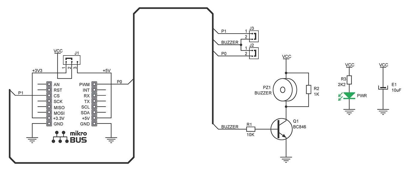
We are reporting the BUZZ click schematic from its manual in order to make some considerations.
- VCC is selectable through a soldered 0Ω resistor; available value are 3.3V and 5V which is the default one (see J1). From here on out VCC means 5V.
- PWR_LED is powered by VCC so it could be considered as a “Power ON” indicator.
- piezo is driven by a transistor and its base could be interconnected to a generic IO PIN (i.e. CS) or to PWM (see J2 and J3). The default input PIN is PWM.
- Using the PWM is possible to generate sounds at different frequencies.
Generating tones using PWM
As said applying an AC voltage to our piezo, it will vibrate producing a pressure wave (i.e. sound). Furthermore the vibration frequency and so the sound frequency will be the same of the input signal frequency. According to Fourier theory and inverse piezoelectricity principle, using a square wave with half duty cycle tuned on a frequency f0 our buzzer will produce a sound which first harmonic will be placed at f0.
The theory is a little bit more complicated but, making an example, if we will use a PWM with duty cycle 50% and a frequency of 440Hz (i.e. the frequency of the musical note LA aka A4) the produced sound will be a “metallic” LA (very similar to dial tones of telephony). If the AC signal had been a sinusoid instead of a square wave, the sound would have been more “smooth”. The interesting fact is that changing the frequency of our PWM we would be able to generate sound at any frequency.
Real case
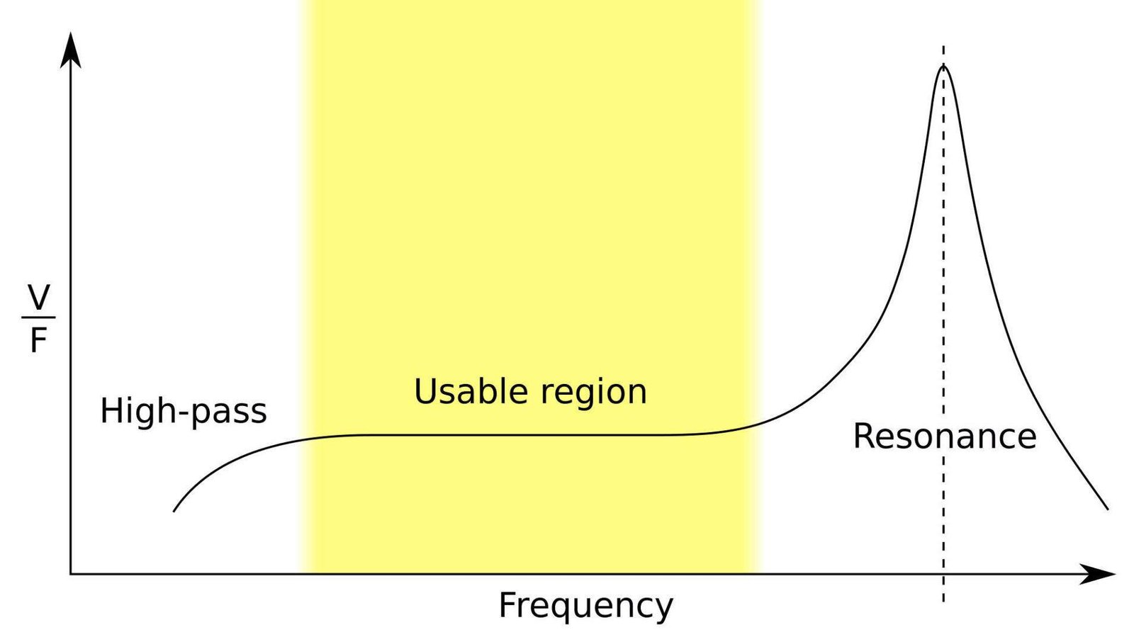
Of course there are some limits. First of all, the common hearing range is 20 Hz~20 kHz and tones outside this range would not be heared. In second place, the frequency response of our piezo is not uniform: it has a resonant peak that in our case is placed at 3.8 kHz, a quasi-uniform range before this frequency and it cuts both low frequencies (near the DC) and frequencies slightly greater than the resonant frequency.
This means, using this buzzer, we will not be able to play sound at high frequency (like ultrasound) but we will have a good and uniform gain in the musical notes range A1~A7 (corresponding to 55~3520 Hz).
Further readings
For those interested in the theory insight the piezo, you need to know that another main use of this components are crystal oscillator and that its impedance could be described by an equivalent model you can found out on this article of Wikipedia. Using this model, would be simple to deduce how the frequency response of Fig.3 has been obtained: according to the voltage divider principle, the higher is the equivalent impedance the higher would be the voltage transferred to the piezo.
Demo explained
The project has two threads: Thread1()) and main(). The former just blinks a LED, the latter is the core of our project. Note that the purpose of Thread1() is to make evident if ChibiOS is still alive or not.
The main() initializes the system, creates Thread1() and starts both SerialUSB Driver and PWM Driver, than it enters in its loop. Note that we have defined different frequencies related to the musical notes from C5 to B6.
In its loop main() read a character with a timeout. If the character is among the allowed (a, s, d, f, g, h and j) then PWM frequency will be changed and buzzer enabled: this makes the buzzer to produce a new tone. Note that if chnReadTimeout() goes timeout or if the character is different from the allowed ones PWM is disabled and buzzer falls silent.
/*
PLAY Embedded demos - Copyright (C) 2014-2016 Rocco Marco Guglielmi
This file is part of PLAY Embedded demos.
Licensed under the Apache License, Version 2.0 (the "License");
you may not use this file except in compliance with the License.
You may obtain a copy of the License at
http://www.apache.org/licenses/LICENSE-2.0"
Unless required by applicable law or agreed to in writing, software
distributed under the License is distributed on an "AS IS" BASIS,
WITHOUT WARRANTIES OR CONDITIONS OF ANY KIND, either express or implied.
See the License for the specific language governing permissions and
limitations under the License.
*/
#include "ch.h"
#include "hal.h"
#include "chprintf.h"
#include "usbcfg.h"
#define C5 1911
#define D5 1703
#define E5 1517
#define F5 1432
#define G5 1275
#define A6 1136
#define B6 1012
static BaseAsynchronousChannel * chnp = (BaseAsynchronousChannel*) &SDU1;
static uint8_t note, rsize;
static msg_t msg;
static PWMConfig pwmcfg = {
1000000, /* 1MHz PWM clock frequency. */
100, /* Initial PWM period 1ms. */
NULL,
{
{PWM_OUTPUT_ACTIVE_LOW, NULL},
{PWM_OUTPUT_DISABLED, NULL},
{PWM_OUTPUT_DISABLED, NULL},
{PWM_OUTPUT_DISABLED, NULL}
},
0,
0
};
/*
* This is a periodic thread that does absolutely nothing except flashing
* a LED.
*/
static THD_WORKING_AREA(waThread1, 128);
static THD_FUNCTION(Thread1, arg) {
(void)arg;
chRegSetThreadName("blinker");
while (true) {
palTogglePad(GPIOE, GPIOE_LED1);
chThdSleepMilliseconds(250);
}
}
/*
* Application entry point.
*/
int main(void) {
/*
* System initializations.
* - HAL initialization, this also initializes the configured device drivers
* and performs the board-specific initializations.
* - Kernel initialization, the main() function becomes a thread and the
* RTOS is active.
*/
halInit();
chSysInit();
/* Creates the example thread. */
chThdCreateStatic(waThread1, sizeof(waThread1), NORMALPRIO - 1, Thread1, NULL);
/*
* Initializes a serial-over-USB CDC driver.
*/
sduObjectInit(&SDU1);
sduStart(&SDU1, &serusbcfg);
/*
* Activates the USB driver and then the USB bus pull-up on D+.
* Note, a delay is inserted in order to not have to disconnect the cable
* after a reset.
*/
usbDisconnectBus(serusbcfg.usbp);
chThdSleepMilliseconds(1500);
usbStart(serusbcfg.usbp, &usbcfg);
usbConnectBus(serusbcfg.usbp);
chThdSleepMilliseconds(2000);
/*
* Normal main() thread activity, in this demo it does nothing except
* sleeping in a loop and check the button state.
*/
pwmStart(&PWMD1, &pwmcfg);
while (TRUE) {
rsize = chnReadTimeout(chnp, ¬e, 1, MS2ST(600));
if( rsize == 1){
msg = chnPutTimeout(chnp, note, MS2ST(600));
switch(note){
case 'a':
pwmChangePeriod(&PWMD1, C5);
pwmEnableChannel(&PWMD1, 0, PWM_PERCENTAGE_TO_WIDTH(&PWMD1, 5000));
break;
case 's':
pwmChangePeriod(&PWMD1, D5);
pwmEnableChannel(&PWMD1, 0, PWM_PERCENTAGE_TO_WIDTH(&PWMD1, 5000));
break;
case 'd':
pwmChangePeriod(&PWMD1, E5);
pwmEnableChannel(&PWMD1, 0, PWM_PERCENTAGE_TO_WIDTH(&PWMD1, 5000));
break;
case 'f':
pwmChangePeriod(&PWMD1, F5);
pwmEnableChannel(&PWMD1, 0, PWM_PERCENTAGE_TO_WIDTH(&PWMD1, 5000));
break;
case 'g':
pwmChangePeriod(&PWMD1, G5);
pwmEnableChannel(&PWMD1, 0, PWM_PERCENTAGE_TO_WIDTH(&PWMD1, 5000));
break;
case 'h':
pwmChangePeriod(&PWMD1, A6);
pwmEnableChannel(&PWMD1, 0, PWM_PERCENTAGE_TO_WIDTH(&PWMD1, 5000));
break;
case 'j':
pwmChangePeriod(&PWMD1, B6);
pwmEnableChannel(&PWMD1, 0, PWM_PERCENTAGE_TO_WIDTH(&PWMD1, 5000));
break;
default:
pwmDisableChannel(&PWMD1, 0);
break;
}
}
else{
pwmDisableChannel(&PWMD1, 0);
}
}
}
Project used in this tutorial
This project has been tested under ChibiOS/RT 3.1.1 (release 16.1) using ChibiStudio Preview 16. For those that are using oldest version of ChibiStudio note that both ChibiOS relative path and USB configuration files could be different. In case of errors like “No rules to make target” look carefully at makefile or contact us.
Description Resource Path Location Type
#error “the USB OTG driver requires a 48MHz clock” hal_usb_lld.h /RT-STM32F446ZE-NUCLEO144buzz/os/hal/ports/STM32/LLD/OTGv1 line 245 C/C++ Problem
Error with USB CDC.. Any solution to this error??
You have to configure the Clock tree properly acting on the mcuconf.h. I suggest you to refer to the reference manual of your mcu.
Hello,
I’ve replaced board files with my stm32f446 board files.
I’m getting an error “no rule to make target”
Description Resource Path Location Type
make: *** No rule to make target ‘../../chibios191/os/common/startup/ARMCMx/compilers/GCC/rules.mk’. Stop. RT-STM32F407-MIKROE-CLICKER2-BUZZ C/C++ Problem
Theres no rules.mk in that file location.
Where is located the project?
RT-STM32F407-MIKROE-CLICKER2-BUZZ
I’ve downloaded this file from downloads page and replaced with my board files and changed makefile for stm32f446ze and added usbcfg.c to the make file.
Hi.. The code compiles without any error after making changes for my board Nucleo-446ZE.
After uploading the code.. the led blinks 3 times.
so I changed the delay of 1500 to 15000
Any solution.
If your board is not using the USB-CDC use the Serial Driver instead.