
Hands-on exercises with LEDs and ChibiOS PAL
Introduction
Digital outputs are an essential part of embedded systems development, and one of the best ways to experiment with them is by using LEDs. In this article, we will take a hands-on approach to digital output using LEDs hooked together with resistors as a peripheral. Along the way, we will explain how LEDs work, how to connect them to your microcontroller, and how to generate precise digital waveforms by combining the PAL driver with the real-time capabilities of ChibiOS/RT.
If you’re not familiar with the theory behind digital outputs, we recommend that you check out our previous article, Mastering GPIOs with ChibiOS PAL: a practical guide that gets covered the working principles of GPIOs and the related API of the PAL driver in ChibiOS/RT HAL. Additionally, if you need a refresher on logic levels, push-pull and open-drain configurations, we suggest reviewing the Fundamentals of Digital Circuitry.
In the upcoming exercises, we will be making extensive use of LEDs. If you are new to working with LEDs, we encourage you to read the article titled A complete overview of LEDs: from theory to applications for a comprehensive understanding of the theory associated with LEDs. However, rest assured that any necessary information will be recalled in each exercise, so you can decide to read it upfront or refer to it as needed.
In this article, we will be using the Analog Devices SDP-K1 evaluation kit. Please note that you can use any other microcontroller supported by ChibiOS, as long as you remain attentive to the differences in routing connections and configuring GPIOs. This will ensure a smooth and successful project experience.
By the end of this article, you’ll have a solid understanding of how to generate precise digital output using LEDs with ChibiOS PAL, as well as how to apply these concepts to your own projects.
Strategies for effective problem solving
One of the fundamental principles I always adhere to when working with new projects is to establish a foundation of certainty and rely on it throughout the understanding and debugging process. In this particular case, the task can range from extremely simple to extremely complex, depending on your level of experience. We will assemble circuits on a breadboard and then write a piece of software to control it. Numerous issues can arise during this process both on the hardware and software side therefore, it is crucial to avoid debugging hardware and software simultaneously. Adopting this approach will prove invaluable throughout your career as an embedded developer.
The strategy here is to connect the hardware first, ensuring that everything is set up correctly before proceeding with the software. Why is this crucial? Picture spending hours debugging your software, only to find that the problem was due to a loose wire or a burnt-out LED. When debugging your application, it’s wise to use a divide-and-conquer approach. By testing your hardware independently, you can confidently focus on your software during debugging, knowing that the issue lies within your code. This can be summarized with a logical statement: “Since my hardware is functioning as expected, the issue must be in my code.”
Exercise 1: External LED connection
We need to develop a program that controls a digital output connected to an external LED through a series resistor, allowing it to blink at a fixed cadence. More precisely, the program will turn on the external LED for a specified duration and then turn it off for the same duration, repeating this process indefinitely.
Setting up the connections
For this exercise, we are going to use a solderless breadboard to connect together some components. If you are unfamiliar with solderless breadboards, it might be helpful to review Breadboards explained: tips and tricks. The initial step is to set up the breadboard with an LED connected in series to a resistor. The resistor serves to limit the current, preventing the LED from burning out. One end of the series branch should be connected to a supply rail from the microcontroller kit, while the other end is connected to a GPIO pin that we will control through software. The schematic of the completed circuit will resemble the diagram provided below:
As mentioned before, it is essential to avoid debugging software and hardware simultaneously. Therefore, the first step we should take is to test our circuit before diving in. There are several potential issues to watch out for:
- LED polarity: The LED’s polarity matters. If connected in reverse polarity, it will not light up.
- Broken LED: If the LED has been used previously and is damaged, it might be challenging to detect at first glance.
- Incorrect resistor size: If the resistor is too large, the LED may not be bright enough, making it difficult to discern any changes. Conversely, if the resistor is too small, the LED could burn out.
- Unstable or faulty connections on the breadboard: These issues can lead to intermittent or incorrect behavior in the circuit.
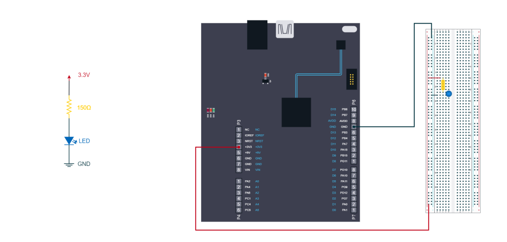
The LED’s polarity and integrity can be verified by conducting a diode test with a digital multimeter. As for the resistor size, it largely depends on your LED’s color, but the reference table provided here can serve as a helpful guide. When powering the LED at 3.3V, as in our example, a resistor value between 100Ω and 300Ω should suffice for a decent light output while ensuring the safe operation of the LED. In this case, I will be using a blue LED paired with an 82Ω series resistor.
To ensure that the circuit has been assembled correctly and the LED functions as intended, you can connect the circuit to the 3.3V and Ground terminals of the SDP-K1 and visually inspect whether the LED turns on with satisfactory brightness. The following image shows how to setup the test.
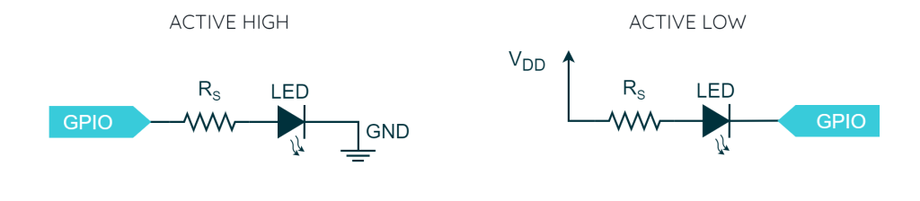
If everything works correctly, we can move to the next step. To do that, you can disconnect one of the two Dupont wires connected to the supply rails and connect it to a GPIO pin. If you connect the GPIO to the rail that was previously connected to the 3.3V supply, you are implementing an active-high logic. Conversely, if you connect the GPIO to the rail that was formerly connected to the Ground, you are establishing an active-low logic.
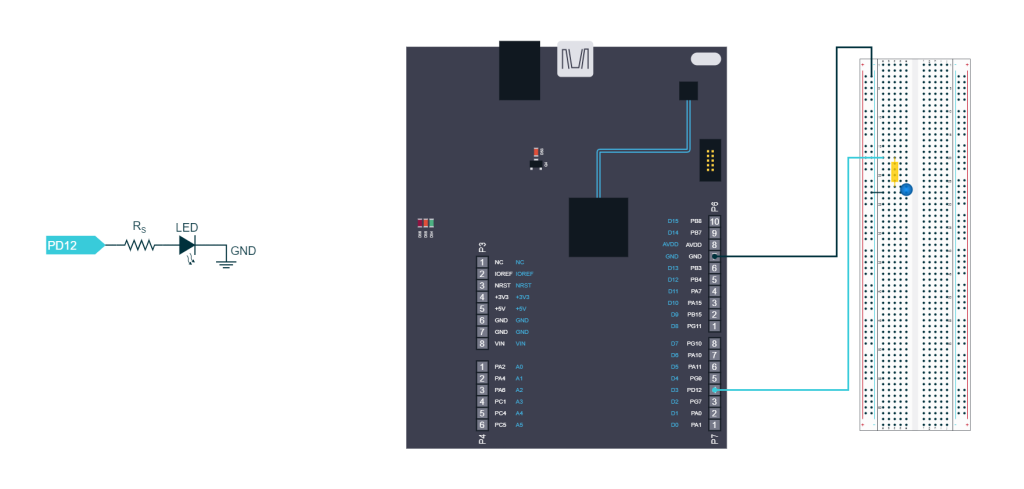
In what follows, we will be using pin D3 of the Arduino connector, which corresponds to PD12 of the SDP-K1, as the GPIO connected to the LED line in an active-high configuration. The setup is illustrated in the image below.
Implementing the firmware
The most straightforward solution we can implement is a single-threaded application that toggles the line associated with PD12 after properly configuring it as a digital output push-pull. However, a smarter choice is to implement a dual-thread application where the second thread controls the blinking of one of the LEDs on the evaluation kit. The rationale behind this choice is that, even if there are issues with our circuit, we can use the onboard LED to quickly determine if the firmware is in execution or not.
#include "ch.h"
#include "hal.h"

/* Definition of a line representing the external LED. */
#define LINE_EXT_LED                LINE_ARD_D3

/*===========================================================================*/
/* Thread 1 related                                                          */
/*===========================================================================*/

/* Thread 1 working area. */
static THD_WORKING_AREA(waThread1, 128);

/**
 * @brief   Parametric thread function.
 */
static THD_FUNCTION(Thread1, arg) {

  (void)arg;
  chRegSetThreadName("blinker");

  while (true) {
    palToggleLine(LINE_LED_GREEN);
    chThdSleepMilliseconds(500);
  }
}

/*===========================================================================*/
/* Application entry point.                                                  */
/*===========================================================================*/

int main(void) {

  /* ChibiOS/HAL and ChibiOS/RT initialization. */
  halInit();
  chSysInit();

  /* Creating the second thread to blink one of the SDP-K1
     LEDs. */
  chThdCreateStatic(waThread1, sizeof(waThread1), NORMALPRIO, Thread1, NULL);

  /* Setting the LED line as digital output push-pull. */
  palSetLineMode(LINE_EXT_LED, PAL_MODE_OUTPUT_PUSHPULL);

  /* main() thread loop. */
  while (true) {
    palToggleLine(LINE_EXT_LED);
    chThdSleepMilliseconds(500);
  }
}
The primary focus of this example is on blinking the external LED connected to the line LINE_ARD_D3 of the SDP-K1 (i.e PD12 of the STM32F469). After including the necessary headers, we define the line representing the external LED as an alias to LINE_ARD_D3.
Thread1 is dedicated to blinking one of the SDP-K1’s onboard LEDs with a cadence of 500 milliseconds, serving as an indicator that the firmware is running properly. After the appropriate system initialization, the main function launches this thread. Subsequently, the main sets the external LED line as a digital output push-pull and enters its loop, where it toggles the GPIO to which our external LED is connected. The following video shows the output of our code.
Exercise 2: Playing with the persistence of view
The objective of this exercise is to experiment with the concept of persistence of vision by creating an application that controls the blinking of an external LED with a 20% duty cycle. The blinking speed will increase progressively. This exercise will allow participants to observe and understand the effects of the persistence of vision in action as the LED blink rate changes.
About the hardware
This exercise can reuse 100% of the previous hardware configuration so we can focus mostly on the software.
Achieving 20% duty cycle
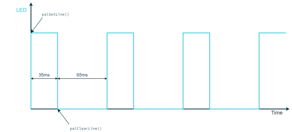
The first thing to look at is how we can achieve the duty cycle of 20%. In reality, this is easier than it looks: it is indeed the combination of the PAL API and the precise timing of RT that decides the speed and the duty cycle of the signal that drives the LED. For example, let us consider the following loop
while (true) {
  palSetLine(LINE_EXT_LED);
  chThdSleepMilliseconds(35);
  palClearLine(LINE_EXT_LED);
  chThdSleepMilliseconds(65);
}
In this code example, the LED is turned on, and then the thread sleeps before turning off the LED, therefore it stays on for 35 milliseconds. Similarly, the LED stays off for 65 ms. Thanks to the reliability of ChibiOS/RT, the signal on the LED line will be a square wave with a period of 100 ms (35ms + 65ms) and a duty cycle of 35% (35ms / 100ms).
However, there are limitations to this mechanism:
- If threads with higher priority or ISRs consume all of the CPU resources, this thread may experience latency or may not be executed at all.
- If the sleep durations for this thread are too short for the MCU in use, the overhead caused by the context switch may introduce latency.
In general, as long as we are dealing with low-speed tasks (1 kHz) and the thread priority is chosen appropriately, everything should work fine on the SDP-K1. It is worth noting that there are more efficient ways to generate square waves in ChibiOS, such as using the PWM driver, but we will leave that for another article.
Concluding, in our specific case we are going to have a variable period so our duty needs to be expressed as a function of it. Consequently, to ensure that the duty cycle is 20% we need to implement something like the following code:
while (true) {
  palSetLine(LINE_EXT_LED);
  chThdSleepMicroseconds(current_period / 5);
  palClearLine(LINE_EXT_LED);
  chThdSleepMicroseconds(current_period * 4 / 5);
}
where current_period is a variable representing the period of the square wave.
Changing the period
There are many ways to implement a variable period, but the easiest method is to choose some preselected periods and use another thread to cycle through them. The choice of periods must be made carefully, as the operating system operates at a specific system frequency. This is a configurable option found in the file chconf.h, which is set to 10 kHz for the SDP-K1.
/**
 * @brief   System tick frequency.
 * @details Frequency of the system timer that drives the system ticks. This
 *          setting also defines the system tick time unit.
 */
#if !defined(CH_CFG_ST_FREQUENCY)
#define CH_CFG_ST_FREQUENCY                 10000
#endif
This frequency determines the speed of the hardware timer used by ChibiOS\RT to schedule deadlines and affects the minimum amount of time a thread can sleep, which in this case is 100 microseconds (the inverse of the System tick frequency). To achieve duty cycles of 20% without rounding errors, the chosen periods should be multiples of 500 microseconds ($latex \frac{100}{20}} \cdot 100us)&fg=00313c).
Given these considerations, I have personally chosen the following 8 periods that changed in sequence better show the effect of the persistence of vision.
/* Definition of a line representing the external button. */
#define NUM_OF_PERIODS              8U

/**
 * @brief   Possible periods expressed in microseconds.
 * @note    The system tick frequency in chconf.h is set to 10kHz.
 *          Therefore, the minimum time step that can be used is 100us.
 */
static uint32_t periods[NUM_OF_PERIODS] = {
  200000,                           /* 5 Hz.    */
  100000,                           /* 10 Hz.   */
  50000,                            /* 20 Hz.   */
  30000,                            /* 33.3 Hz. */
  20000,                            /* 50 Hz.   */
  15000,                            /* 66.7 Hz. */
  10000,                            /* 100 Hz.  */
  5000                              /* 200 Hz.  */
};
As per the thread that is going to change the period, this can be done by the thread that blinks the on-board LED as we are not having a time constraint on that and we can choose to make it run as fast as we want.
Exchanging data between threads
In this application, one thread is selecting the period for the other one. This is an example of a situation where communication between two threads is necessary. There are various mechanisms that can be used for this, and we will explore more in the future. For now, since this application is relatively simple, we will start with a basic method: using a shared static variable.
By declaring a static variable in main.c, it becomes visible throughout the entire file. This makes the variable accessible from both threads. However, the access to the variable should be synchronized using a mutex to prevent race conditions. If you don’t know what a race condition is and how a mutex addresses this issue we have a short article about the topic. However, you can skip that for now and know that the access to shared variables needs to be synchronized using a mutex as shown in the following example
#include "ch.h"
#include "hal.h"

/* Shared variable and mutex. */
static uint32_t shared_var;
static mutex_t my_mutex;

static THD_WORKING_AREA(waThread1, 128);
static THD_FUNCTION(Thread1, arg) {
  ...
  while (true) {
    /* Mutual exclusive zone. */
    chMtxLock(&my_mutex);
    shared_var++;
    chMtxUnlock(&my_mutex);
    ...
  }
}

int main(void) {

  /* ChibiOS/HAL and ChibiOS/RT initialization. */
  halInit();
  chSysInit();

  /* Initializing the mutex. */
  chMtxObjectInit(&my_mutex);

  /* Creating the second thread. */
  chThdCreateStatic(waThread1, sizeof(waThread1), NORMALPRIO, Thread1, NULL);

  while (true) {
    /* Mutual exclusive zone. */
    chMtxLock(&my_mutex);
    shared_var--;
    chMtxUnlock(&my_mutex);
    ...
  }
}
Proposed solution
The suggested solution utilizes Thread1 to increment cyclically the index of the array containing the preselected periods. The main thread reads the current period at each cycle and stores it in a local variable. It then blinks the external LED with a duty cycle of 20% and a period based on the value of the local variable.
#include "ch.h"
#include "hal.h"

/* Definition of a line representing the external LED. */
#define LINE_EXT_LED                LINE_ARD_D3

/*===========================================================================*/
/* Thread 1 related                                                          */
/*===========================================================================*/

/* Definition of a line representing the external button. */
#define NUM_OF_PERIODS              8U

/**
 * @brief   Possible periods expressed in microseconds.
 * @note    The system tick frequency in chconf.h is set to 10kHz.
 *          Therefore, the minimum time step that can be used is 100us.
 */
static uint32_t periods[NUM_OF_PERIODS] = {
  200000,                           /* 5 Hz.    */
  100000,                           /* 10 Hz.   */
  50000,                            /* 20 Hz.   */
  30000,                            /* 33.3 Hz. */
  20000,                            /* 50 Hz.   */
  15000,                            /* 66.7 Hz. */
  10000,                            /* 100 Hz.  */
  5000                              /* 200 Hz.  */
};

/**
 * @brief   A variable indicating the index of the period in use.
 */
static uint32_t index = 0;

/**
 * @brief   Mutex to protect the access to the shared variable.
 */
static mutex_t index_mutex;

/* Thread 1 working area. */
static THD_WORKING_AREA(waThread1, 128);

/**
 * @brief   Parametric thread function.
 */
static THD_FUNCTION(Thread1, arg) {

  (void)arg;
  chRegSetThreadName("blinker");

  while (true) {
    palToggleLine(LINE_LED_GREEN);
    chThdSleepMilliseconds(500);

    /* Increasing the index cyclically. The operation
       is protected by a mutex. */
    chMtxLock(&index_mutex);
    index = (index + 1) % NUM_OF_PERIODS;
    chMtxUnlock(&index_mutex);
  }
}

/*===========================================================================*/
/* Application entry point.                                                  */
/*===========================================================================*/

static uint32_t current_period;

int main(void) {

  /* ChibiOS/HAL and ChibiOS/RT initialization. */
  halInit();
  chSysInit();

  /* Creating a thread to blink one of the SDP-K1 LEDs and changes the period
     of the squarewave.  */
  chThdCreateStatic(waThread1, sizeof(waThread1), NORMALPRIO, Thread1, NULL);

  /* Setting the LED line as digital output push-pull. */
  palSetLineMode(LINE_EXT_LED, PAL_MODE_OUTPUT_PUSHPULL);

  /* Initializing the mutex. */
  chMtxObjectInit(&index_mutex);

  /* main() thread loop. */
  while (true) {
    /* Getting the current period. This avoids makes sure that the period
       doesn't change in the middle of the square wave. The operation
       is protected by a mutex. */
    chMtxLock(&index_mutex);
    current_period = periods[index];
    chMtxUnlock(&index_mutex);

    palSetLine(LINE_EXT_LED);
    chThdSleepMicroseconds(current_period / 5);
    palClearLine(LINE_EXT_LED);
    chThdSleepMicroseconds(current_period * 4 / 5);
  }
}
The effect of this exercise is quite a show but unfortunately complicated to show in a video because of the quantization effect introduced by the digital camera: you have to try it on your own.
Exercise 3: RGB LED simple color wheel
Create a program that cycles through a simple color wheel using an external RGB LED connected to a microcontroller. The color wheel should display the following colors in sequence: Red, Orange, Green, Azure, Blue, Purple, Red, and so on. The objective is to demonstrate the control of an RGB LED to generate different colors using GPIO pins on a microcontroller.
About the hardware
In this exercise, instead of using a solderless breadboard to connect components, we will use a breakout board that already hosts an RGB LED and the resistors for each junction. In this specific case, a common anode RGB LED is being used, which means the logic here will be Active-Low. The schematic of the breakout board is illustrated in the following diagram.
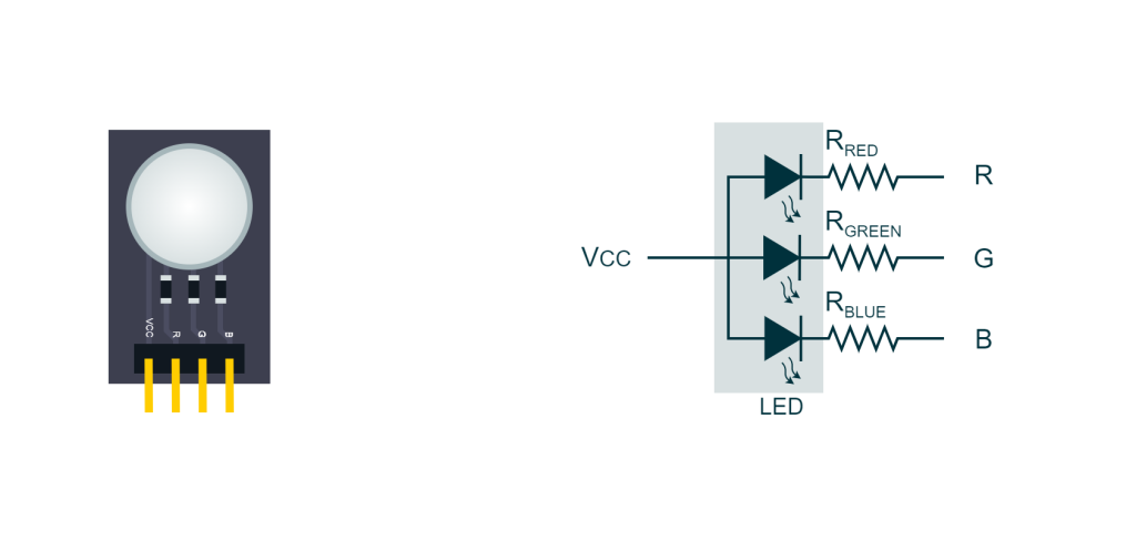
The connections to the microcontroller are quite straightforward as shown in the following picture

Once again, with the given LED configuration, turning off a line would mean turning on the associated junction, and vice versa, in accordance with the active low logic.
Color wheel
By activating specific junctions, we can achieve up to 7 colors with an RGB LED. The following table, taken from the article A complete overview of LEDs: from theory to applications, summarizes the possibilities:
| Color | Red junction | Green junction | Blue junction |
|---|---|---|---|
| Red | ON | OFF | OFF |
| Green | OFF | ON | OFF |
| Blue | OFF | OFF | ON |
| Orange | ON | ON | OFF |
| Cyan | OFF | ON | ON |
| Magenta | ON | OFF | ON |
| White | ON | ON | ON |
Proposed solution
The solution proposed is a dual-thread application where one of the threads is there only to blink the onboard LED. The main instead after configuring properly the lines associated with the RGB LED enters into his loop: here the RGB LED is cycled through six different colors by acting on the specific output lines.
The loop uses the index variable to determine which color to set the LED to by enabling or disabling the corresponding red, green, and blue junctions. The setLed function is used for this purpose. After setting the LED to the current color, the index variable is incremented and wrapped around modulo 6 to cycle through the colors. Finally, the thread sleeps for 250 milliseconds before repeating the loop and moving on to the next color.
#include "ch.h"
#include "hal.h"

/* Definition of a line representing the external LED. */
#define LINE_EXT_LED_RED            LINE_ARD_D3
#define LINE_EXT_LED_GREEN          LINE_ARD_D4
#define LINE_EXT_LED_BLUE           LINE_ARD_D5

/*===========================================================================*/
/* Thread 1 related                                                          */
/*===========================================================================*/

/* Thread 1 working area. */
static THD_WORKING_AREA(waThread1, 128);

/**
 * @brief   Parametric thread function.
 */
static THD_FUNCTION(Thread1, arg) {

  (void)arg;
  chRegSetThreadName("blinker");

  while (true) {
    palToggleLine(LINE_LED_GREEN);
    chThdSleepMilliseconds(500);
  }
}

/*===========================================================================*/
/* LED related API.                                                          */
/*===========================================================================*/

/**
 * @brief   Defines the logic of the LED and consequently the behaviour of
 *          the function setLed().
 */
#define LED_ACTIVE_HIGH             FALSE

/**
 * @brief   This variable indicate which color is going to be set.
 */
static uint32_t index = 0;

/**
 * @brief   Sets the RGB LED accordingly to the parameters passed.
 * @notes   The parameter can be true or false.
 *
 * @param[in] r         the status of the red junction
 * @param[in] g         the status of the green junction
 * @param[in] b         the status of the blue junction
 *
 */
#if LED_ACTIVE_HIGH
#define setLed(r, g, b){                  \
  palWriteLine(LINE_EXT_LED_RED, (r));    \
  palWriteLine(LINE_EXT_LED_GREEN, (g));  \
  palWriteLine(LINE_EXT_LED_BLUE, (b));   \
}
#else
#define setLed(r, g, b){                  \
  palWriteLine(LINE_EXT_LED_RED, !(r));   \
  palWriteLine(LINE_EXT_LED_GREEN, !(g)); \
  palWriteLine(LINE_EXT_LED_BLUE, !(b));  \
}
#endif

/*===========================================================================*/
/* Application entry point.                                                  */
/*===========================================================================*/

int main(void) {

  /* ChibiOS/HAL and ChibiOS/RT initialization. */
  halInit();
  chSysInit();

  /* Creating a thread to blink one of the SDP-K1 LEDs and changes the period
     of the squarewave.  */
  chThdCreateStatic(waThread1, sizeof(waThread1), NORMALPRIO, Thread1, NULL);

  /* Preconfiguring the LED as off. */
  palSetLine(LINE_EXT_LED_RED);
  palSetLine(LINE_EXT_LED_GREEN);
  palSetLine(LINE_EXT_LED_BLUE);

  /* Setting the LED line as digital output push-pull. */
  palSetLineMode(LINE_EXT_LED_RED, PAL_MODE_OUTPUT_PUSHPULL);
  palSetLineMode(LINE_EXT_LED_GREEN, PAL_MODE_OUTPUT_PUSHPULL);
  palSetLineMode(LINE_EXT_LED_BLUE, PAL_MODE_OUTPUT_PUSHPULL);


  /* main() thread loop. */
  while (true) {

    if(index == 0) {
      setLed(TRUE, FALSE, FALSE);
    }
    else if(index == 1) {
      setLed(TRUE, TRUE, FALSE);
    }
    else if(index == 2) {
      setLed(FALSE, TRUE, FALSE);
    }
    else if(index == 3) {
      setLed(FALSE, TRUE, TRUE);
    }
    else if(index == 4) {
      setLed(FALSE, FALSE, TRUE);
    }
     else if(index == 5) {
      setLed(TRUE, FALSE, TRUE);
    }

    index = (index + 1) % 6;

    chThdSleepMilliseconds(250);
  }
}
Note that the LED_ACTIVE_HIGH macro accounts for the LED logic by altering the implementation of the setLed() macro to reflect the configuration of the RGB LED. The current code is configured for a common anode LED, which, by definition, is behaving as active-low logic. If you are using a common cathode LED, you may want to set LED_ACTIVE_HIGH to TRUE to adapt the implementation accordingly.
The following video demonstrates the final result
Exercise 4: RGB LED continuous color wheel
Create a continuous color wheel on the RGB LED by leveraging the persistence of vision and the properties of square waves. This will be accomplished by combining the PAL driver with ChibiOS/RT’s reliable timing. Your task is to develop an application that smoothly transitions through the colors of the wheel while maintaining accurate timing and synchronization.
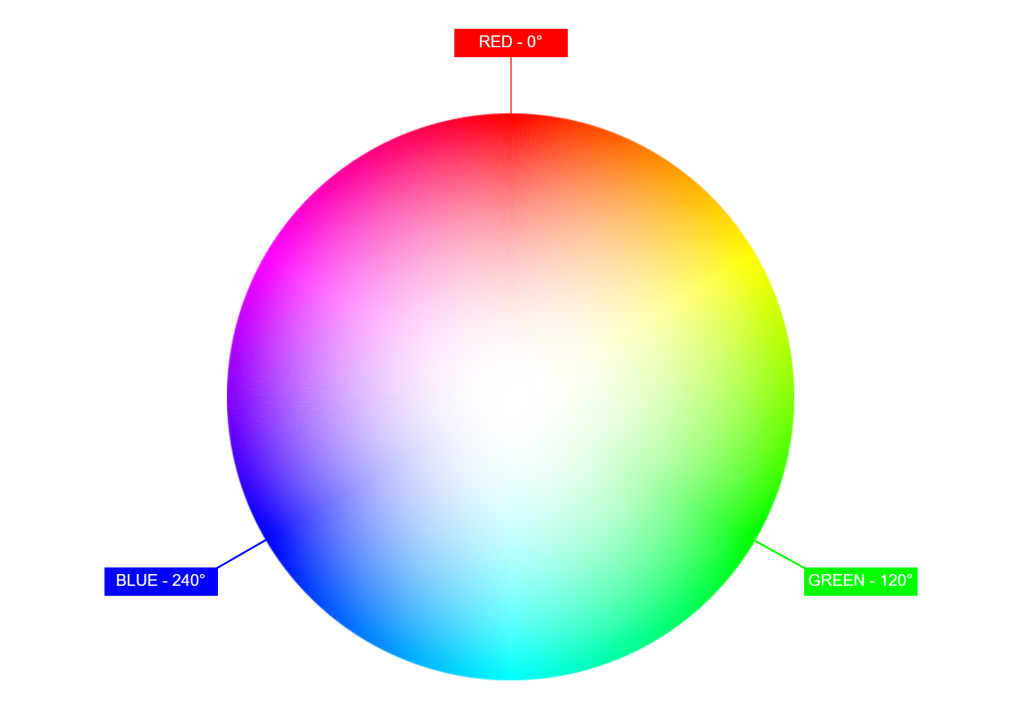
Color wheel explained
A color wheel is a visual representation of colors arranged in a circular order, showcasing the relationships between primary, secondary, and tertiary colors. It is a useful tool for understanding color harmony and creating pleasing color schemes.
In the context of an RGB LED, a color wheel is obtained by mixing only two colors at a time. For example, you can mix red and green to create yellow, green and blue to create cyan, or red and blue to create magenta as we did in the previous example by turning on two junctions at a time.
When you add the third color, the resulting hue moves towards white, effectively desaturating the color wheel. Instead of abruptly turning on and off the junctions, this time we want to smoothly shift between two colors adjusting the intensity of each color. In this way, we can create a continuous color wheel that showcases a wide range of hues.
Leveraging the persistence of vision
In this experiment, we will build upon the concepts of persistence of vision explored in a previous article to create a more complex system. This time, we need to manage three junctions instead of one and continuously shift the duty cycle over time.
Visualizing the color wheel as a circle and navigating it using an angle, we can observe that the wheel is divided into three sections:
- From 0° to 120°, we transition from red to green
- From 120° to 240°, we transition from green to blue
- From 240° to 360°, we transition from blue to red
In each of these intervals, one color is fading, another is intensifying, and the third one is off. The duty cycle of each junction will have the same angular behavior but shifted by 120°. This leads to the expected representation of the duty cycle of each color as a function of the angle.
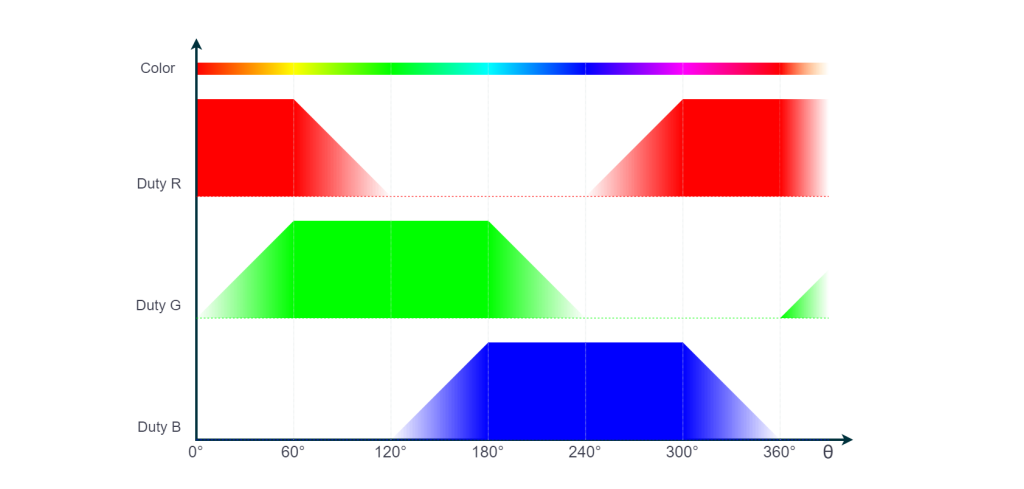
Let us derive the behavior of the duty by looking at one of the functions, for example, the one of the green. The range is divided into 6 intervals
| Interval | Duty |
|---|---|
| 0°-60° | ramp up linearly from 0% to 100% |
| 60°-120° | 100% |
| 120°-180° | 100% |
| 180°-240° | ramp down linearly from 100% to 0% |
| 240°-300° | 0% |
| 300°-360° | 0% |
To avoid flickering in the LED, we want to have each junction blink at 100Hz. This means that the period of each thread needs to be 10 milliseconds. In other words, when the duty cycle of a junction is X%, that junction is going to stay on for X% of 10ms and off for the remaining time. The most suitable way to represent the duty cycle is the on-time expressed in microseconds, where 100% is 10000us.
For instance, if the duty cycle at a specific time is 8500, it means our thread is going to keep the LED on for 8500us and off for 1500us. The loop will therefore look like this:
  while (true) {
    ledOn(LINE_LED);
    chThdSleepMicroseconds(curr_duty);
    ledOff(LINE_LED);
    chThdSleepMicroseconds(10000 - curr_duty);
  }
There are several ways to obtain the duty cycle given the angle. One possible approach is to implement a function that takes an angle from 0 to 359 and calculates the duty cycle. This function will determine the interval in which the angle lies and calculate the duty accordingly.
uint32_t getDuty(uint32_t angle) {

  uint32_t duty;

  /* Wrapping the angle to 360. */
  angle %= 360;

  if(angle < 60) {
    /* Linear ramp from 0 to 10000. */
    duty = 10000 * angle / 60;
  }
  else if(angle < 180) {
    duty = 10000;
  }
  else if(angle < 240) {
    duty = (240 - angle) * 10000 / 60;
  }
  else {
    duty = 0;
  }

  /* The system tick has a period of 100us. Need to round to
     avoid errors. */
  duty = duty - (duty % 100);
  return duty;
}
Since this function will be executed frequently, it makes sense to adopt an alternative approach, such as a lookup table. The following table consists of an array with 360 elements, storing the duty cycle value for each angle.
/**
 * @brief   Duty cycle lookup table.
 */
static const uint32_t led_lookup[360] = {
  0x0000, 0x00C8, 0x012C, 0x01F4, 0x02BC, 0x0320, 0x03E8, 0x04B0,
  0x0578, 0x05DC, 0x06A4, 0x076C, 0x07D0, 0x0898, 0x0960, 0x09C4,
  0x0A8C, 0x0B54, 0x0BB8, 0x0C80, 0x0D48, 0x0DAC, 0x0E74, 0x0F3C,
  0x0FA0, 0x1068, 0x1130, 0x11F8, 0x125C, 0x1324, 0x13EC, 0x1450,
  0x1518, 0x15E0, 0x16A8, 0x170C, 0x17D4, 0x189C, 0x1900, 0x19C8,
  0x1A90, 0x1AF4, 0x1BBC, 0x1C84, 0x1CE8, 0x1DB0, 0x1E78, 0x1F40,
  0x1FA4, 0x206C, 0x2134, 0x2198, 0x2260, 0x2328, 0x238C, 0x2454,
  0x251C, 0x2580, 0x2648, 0x2710, 0x2710, 0x2710, 0x2710, 0x2710,
  0x2710, 0x2710, 0x2710, 0x2710, 0x2710, 0x2710, 0x2710, 0x2710,
  0x2710, 0x2710, 0x2710, 0x2710, 0x2710, 0x2710, 0x2710, 0x2710,
  0x2710, 0x2710, 0x2710, 0x2710, 0x2710, 0x2710, 0x2710, 0x2710,
  0x2710, 0x2710, 0x2710, 0x2710, 0x2710, 0x2710, 0x2710, 0x2710,
  0x2710, 0x2710, 0x2710, 0x2710, 0x2710, 0x2710, 0x2710, 0x2710,
  0x2710, 0x2710, 0x2710, 0x2710, 0x2710, 0x2710, 0x2710, 0x2710,
  0x2710, 0x2710, 0x2710, 0x2710, 0x2710, 0x2710, 0x2710, 0x2710,
  0x2710, 0x2710, 0x2710, 0x2710, 0x2710, 0x2710, 0x2710, 0x2710,
  0x2710, 0x2710, 0x2710, 0x2710, 0x2710, 0x2710, 0x2710, 0x2710,
  0x2710, 0x2710, 0x2710, 0x2710, 0x2710, 0x2710, 0x2710, 0x2710,
  0x2710, 0x2710, 0x2710, 0x2710, 0x2710, 0x2710, 0x2710, 0x2710,
  0x2710, 0x2710, 0x2710, 0x2710, 0x2710, 0x2710, 0x2710, 0x2710,
  0x2710, 0x2710, 0x2710, 0x2710, 0x2710, 0x2710, 0x2710, 0x2710,
  0x2710, 0x2710, 0x2710, 0x2710, 0x2710, 0x2710, 0x2710, 0x2710,
  0x2710, 0x2710, 0x2710, 0x2710, 0x2710, 0x2648, 0x2580, 0x251C,
  0x2454, 0x238C, 0x2328, 0x2260, 0x2198, 0x2134, 0x206C, 0x1FA4,
  0x1F40, 0x1E78, 0x1DB0, 0x1CE8, 0x1C84, 0x1BBC, 0x1AF4, 0x1A90,
  0x19C8, 0x1900, 0x189C, 0x17D4, 0x170C, 0x16A8, 0x15E0, 0x1518,
  0x1450, 0x13EC, 0x1324, 0x125C, 0x11F8, 0x1130, 0x1068, 0x0FA0,
  0x0F3C, 0x0E74, 0x0DAC, 0x0D48, 0x0C80, 0x0BB8, 0x0B54, 0x0A8C,
  0x09C4, 0x0960, 0x0898, 0x07D0, 0x076C, 0x06A4, 0x05DC, 0x0578,
  0x04B0, 0x03E8, 0x0320, 0x02BC, 0x01F4, 0x012C, 0x00C8, 0x0000,
  0x0000, 0x0000, 0x0000, 0x0000, 0x0000, 0x0000, 0x0000, 0x0000,
  0x0000, 0x0000, 0x0000, 0x0000, 0x0000, 0x0000, 0x0000, 0x0000,
  0x0000, 0x0000, 0x0000, 0x0000, 0x0000, 0x0000, 0x0000, 0x0000,
  0x0000, 0x0000, 0x0000, 0x0000, 0x0000, 0x0000, 0x0000, 0x0000,
  0x0000, 0x0000, 0x0000, 0x0000, 0x0000, 0x0000, 0x0000, 0x0000,
  0x0000, 0x0000, 0x0000, 0x0000, 0x0000, 0x0000, 0x0000, 0x0000,
  0x0000, 0x0000, 0x0000, 0x0000, 0x0000, 0x0000, 0x0000, 0x0000,
  0x0000, 0x0000, 0x0000, 0x0000, 0x0000, 0x0000, 0x0000, 0x0000,
  0x0000, 0x0000, 0x0000, 0x0000, 0x0000, 0x0000, 0x0000, 0x0000,
  0x0000, 0x0000, 0x0000, 0x0000, 0x0000, 0x0000, 0x0000, 0x0000,
  0x0000, 0x0000, 0x0000, 0x0000, 0x0000, 0x0000, 0x0000, 0x0000,
  0x0000, 0x0000, 0x0000, 0x0000, 0x0000, 0x0000, 0x0000, 0x0000,
  0x0000, 0x0000, 0x0000, 0x0000, 0x0000, 0x0000, 0x0000, 0x0000,
  0x0000, 0x0000, 0x0000, 0x0000, 0x0000, 0x0000, 0x0000, 0x0000,
  0x0000, 0x0000, 0x0000, 0x0000, 0x0000, 0x0000, 0x0000
};
Managing three junctions
Each junction needs to be managed independently with a separate thread that blinks the LED with the proper cadency. However, the three threads will be extremely similar with a due exception for the line to handle and the offset with which the table is accessed. This is the right moment to reuse some of the concepts shown in Parametric Threads with ChibiOS and create a parametric thread that will receive the line and the offset as an argument.
/**
 * @brief   LED configuration structure.
 */
typedef struct {
  /**
   * @brief Line associated to LED
   */
  ioline_t                  led;
  /**
   * @brief Offset.
   */
  uint32_t                  offset;
} ThreadConfig_t;

/**
 * @brief   Parametric thread function.
 */
static THD_FUNCTION(ThreadLed, arg) {

  uint32_t local_angle;

  /* Using a temporary variable to make our code more readable. */
  ThreadConfig_t* mycfg = (ThreadConfig_t*)arg;

  while (true) {

    /* Calculating the local angle.The operation
       is protected by a mutex. */
    chMtxLock(&curr_angle_mtx);
    local_angle = (curr_angle + mycfg->offset) % 360;
    chMtxUnlock(&curr_angle_mtx);

    /* Applying the proper duty cycle. */
    if(led_lookup[local_angle] > 0) {
      ledOn(mycfg->led);
      chThdSleepMicroseconds(led_lookup[local_angle]);
    }
    if((10000 - led_lookup[local_angle]) > 0) {
      ledOff(mycfg->led);
      chThdSleepMicroseconds(10000 - led_lookup[local_angle]);
    }
  }
}
There are only a few notes here to add. The variable curr_angle is a variable shared between the threads and as such need to be protected with a mutex. The variable is increased circularly over time by the main thread and it is used to calculate the local_angle that is the angle relative to the specific junction.
Proposed solution
The following code presents the complete solution. Please note that this code is not designed for efficiency, as managing the three threads with a time granularity of 100us will generate a significant number of interrupts to handle. That said, you might want to run this code with optimizations enabled in the makefile. In a future article, we will explore how to accomplish the same task more efficiently using the PWM driver in ChibiOS, which leverages dedicated microcontroller peripherals to generate square waves.
#include "ch.h"
#include "hal.h"

/* Definition of a line representing the external LED. */
#define LINE_EXT_LED_RED            LINE_ARD_D3
#define LINE_EXT_LED_GREEN          LINE_ARD_D4
#define LINE_EXT_LED_BLUE           LINE_ARD_D5

/*===========================================================================*/
/* Thread 1 related                                                          */
/*===========================================================================*/

/* Thread 1 working area. */
static THD_WORKING_AREA(waThread1, 128);

/**
 * @brief   Parametric thread function.
 */
static THD_FUNCTION(Thread1, arg) {

  (void)arg;
  chRegSetThreadName("blinker");

  while (true) {
    palToggleLine(LINE_LED_GREEN);
    chThdSleepMilliseconds(500);
  }
}

/*===========================================================================*/
/* LED related API.                                                          */
/*===========================================================================*/

/**
 * @brief   Defines the logic of the LED and consequently the behaviour of
 *          the function setLed().
 */
#define LED_ACTIVE_HIGH             FALSE

/**
 * @brief   This variable indicate the current angle
 * .
 */
static uint32_t curr_angle = 0;

/**
 * @brief   Mutex to protect the access to the shared variable.
 */
static mutex_t curr_angle_mtx;

/**
 * @brief   Sets the LED ON
 *
 * @param[in] line      the line to handle.
 *
 */
#if LED_ACTIVE_HIGH
#define ledOn(line)                 palSetLine(line)
#else
#define ledOn(line)                 palClearLine(line)
#endif

/**
 * @brief   Sets the LED off
 *
 * @param[in] line      the line to handle.
 *
 */
#if LED_ACTIVE_HIGH
#define ledOff(line)                 palClearLine(line)
#else
#define ledOff(line)                 palSetLine(line)
#endif

/**
 * @brief   Duty cycle lookup table.
 */
static const uint32_t led_lookup[360] = {
  0x0000, 0x00C8, 0x012C, 0x01F4, 0x02BC, 0x0320, 0x03E8, 0x04B0,
  0x0578, 0x05DC, 0x06A4, 0x076C, 0x07D0, 0x0898, 0x0960, 0x09C4,
  0x0A8C, 0x0B54, 0x0BB8, 0x0C80, 0x0D48, 0x0DAC, 0x0E74, 0x0F3C,
  0x0FA0, 0x1068, 0x1130, 0x11F8, 0x125C, 0x1324, 0x13EC, 0x1450,
  0x1518, 0x15E0, 0x16A8, 0x170C, 0x17D4, 0x189C, 0x1900, 0x19C8,
  0x1A90, 0x1AF4, 0x1BBC, 0x1C84, 0x1CE8, 0x1DB0, 0x1E78, 0x1F40,
  0x1FA4, 0x206C, 0x2134, 0x2198, 0x2260, 0x2328, 0x238C, 0x2454,
  0x251C, 0x2580, 0x2648, 0x2710, 0x2710, 0x2710, 0x2710, 0x2710,
  0x2710, 0x2710, 0x2710, 0x2710, 0x2710, 0x2710, 0x2710, 0x2710,
  0x2710, 0x2710, 0x2710, 0x2710, 0x2710, 0x2710, 0x2710, 0x2710,
  0x2710, 0x2710, 0x2710, 0x2710, 0x2710, 0x2710, 0x2710, 0x2710,
  0x2710, 0x2710, 0x2710, 0x2710, 0x2710, 0x2710, 0x2710, 0x2710,
  0x2710, 0x2710, 0x2710, 0x2710, 0x2710, 0x2710, 0x2710, 0x2710,
  0x2710, 0x2710, 0x2710, 0x2710, 0x2710, 0x2710, 0x2710, 0x2710,
  0x2710, 0x2710, 0x2710, 0x2710, 0x2710, 0x2710, 0x2710, 0x2710,
  0x2710, 0x2710, 0x2710, 0x2710, 0x2710, 0x2710, 0x2710, 0x2710,
  0x2710, 0x2710, 0x2710, 0x2710, 0x2710, 0x2710, 0x2710, 0x2710,
  0x2710, 0x2710, 0x2710, 0x2710, 0x2710, 0x2710, 0x2710, 0x2710,
  0x2710, 0x2710, 0x2710, 0x2710, 0x2710, 0x2710, 0x2710, 0x2710,
  0x2710, 0x2710, 0x2710, 0x2710, 0x2710, 0x2710, 0x2710, 0x2710,
  0x2710, 0x2710, 0x2710, 0x2710, 0x2710, 0x2710, 0x2710, 0x2710,
  0x2710, 0x2710, 0x2710, 0x2710, 0x2710, 0x2710, 0x2710, 0x2710,
  0x2710, 0x2710, 0x2710, 0x2710, 0x2710, 0x2648, 0x2580, 0x251C,
  0x2454, 0x238C, 0x2328, 0x2260, 0x2198, 0x2134, 0x206C, 0x1FA4,
  0x1F40, 0x1E78, 0x1DB0, 0x1CE8, 0x1C84, 0x1BBC, 0x1AF4, 0x1A90,
  0x19C8, 0x1900, 0x189C, 0x17D4, 0x170C, 0x16A8, 0x15E0, 0x1518,
  0x1450, 0x13EC, 0x1324, 0x125C, 0x11F8, 0x1130, 0x1068, 0x0FA0,
  0x0F3C, 0x0E74, 0x0DAC, 0x0D48, 0x0C80, 0x0BB8, 0x0B54, 0x0A8C,
  0x09C4, 0x0960, 0x0898, 0x07D0, 0x076C, 0x06A4, 0x05DC, 0x0578,
  0x04B0, 0x03E8, 0x0320, 0x02BC, 0x01F4, 0x012C, 0x00C8, 0x0000,
  0x0000, 0x0000, 0x0000, 0x0000, 0x0000, 0x0000, 0x0000, 0x0000,
  0x0000, 0x0000, 0x0000, 0x0000, 0x0000, 0x0000, 0x0000, 0x0000,
  0x0000, 0x0000, 0x0000, 0x0000, 0x0000, 0x0000, 0x0000, 0x0000,
  0x0000, 0x0000, 0x0000, 0x0000, 0x0000, 0x0000, 0x0000, 0x0000,
  0x0000, 0x0000, 0x0000, 0x0000, 0x0000, 0x0000, 0x0000, 0x0000,
  0x0000, 0x0000, 0x0000, 0x0000, 0x0000, 0x0000, 0x0000, 0x0000,
  0x0000, 0x0000, 0x0000, 0x0000, 0x0000, 0x0000, 0x0000, 0x0000,
  0x0000, 0x0000, 0x0000, 0x0000, 0x0000, 0x0000, 0x0000, 0x0000,
  0x0000, 0x0000, 0x0000, 0x0000, 0x0000, 0x0000, 0x0000, 0x0000,
  0x0000, 0x0000, 0x0000, 0x0000, 0x0000, 0x0000, 0x0000, 0x0000,
  0x0000, 0x0000, 0x0000, 0x0000, 0x0000, 0x0000, 0x0000, 0x0000,
  0x0000, 0x0000, 0x0000, 0x0000, 0x0000, 0x0000, 0x0000, 0x0000,
  0x0000, 0x0000, 0x0000, 0x0000, 0x0000, 0x0000, 0x0000, 0x0000,
  0x0000, 0x0000, 0x0000, 0x0000, 0x0000, 0x0000, 0x0000, 0x0000,
  0x0000, 0x0000, 0x0000, 0x0000, 0x0000, 0x0000, 0x0000
};

/**
 * @brief   LED configuration structure.
 */
typedef struct {
  /**
   * @brief Line associated to LED
   */
  ioline_t                  led;
  /**
   * @brief Offset.
   */
  uint32_t                  offset;
} ThreadConfig_t;

/**
 * @brief   Parametric thread function.
 */
static THD_FUNCTION(ThreadLed, arg) {

  uint32_t local_angle;

  /* Using a temporary variable to make our code more readable. */
  ThreadConfig_t* mycfg = (ThreadConfig_t*)arg;

  while (true) {

    /* Calculating the local angle.The operation
       is protected by a mutex. */
    chMtxLock(&curr_angle_mtx);
    local_angle = (curr_angle + mycfg->offset) % 360;
    chMtxUnlock(&curr_angle_mtx);

    /* Applying the proper duty cycle. */
    if(led_lookup[local_angle] > 0) {
      ledOn(mycfg->led);
      chThdSleepMicroseconds(led_lookup[local_angle]);
    }
    if((10000 - led_lookup[local_angle]) > 0) {
      ledOff(mycfg->led);
      chThdSleepMicroseconds(10000 - led_lookup[local_angle]);
    }
  }
}

/*===========================================================================*/
/* Threads working areas and configurations                                  */
/*===========================================================================*/

/* Threads working areas. */
static THD_WORKING_AREA(waThreadR, 128);
static THD_WORKING_AREA(waThreadG, 128);
static THD_WORKING_AREA(waThreadB, 128);

/* Threads parameters. */
static ThreadConfig_t thdRedCfg = {
  .led = LINE_EXT_LED_RED,
  .offset = 0
};
static ThreadConfig_t thdGreenCfg = {
  .led = LINE_EXT_LED_GREEN,
  .offset = 120
};
static ThreadConfig_t thdBlueCfg = {
  .led = LINE_EXT_LED_BLUE,
  .offset = 240
};

/*===========================================================================*/
/* Application entry point.                                                  */
/*===========================================================================*/

int main(void) {

  /* ChibiOS/HAL and ChibiOS/RT initialization. */
  halInit();
  chSysInit();

  /* Creating a thread to blink one of the SDP-K1 LEDs and changes the period
     of the squarewave.  */
  chThdCreateStatic(waThread1, sizeof(waThread1), NORMALPRIO, Thread1, NULL);

  chThdCreateStatic(waThreadR, sizeof(waThreadR), NORMALPRIO, ThreadLed, &thdRedCfg);
  chThdCreateStatic(waThreadG, sizeof(waThreadG), NORMALPRIO, ThreadLed, &thdGreenCfg);
  chThdCreateStatic(waThreadB, sizeof(waThreadB), NORMALPRIO, ThreadLed, &thdBlueCfg);

  /* Preconfiguring the LED as off. */
  palSetLine(LINE_EXT_LED_RED);
  palSetLine(LINE_EXT_LED_GREEN);
  palSetLine(LINE_EXT_LED_BLUE);

  /* Setting the LED line as digital output push-pull. */
  palSetLineMode(LINE_EXT_LED_RED, PAL_MODE_OUTPUT_PUSHPULL);
  palSetLineMode(LINE_EXT_LED_GREEN, PAL_MODE_OUTPUT_PUSHPULL);
  palSetLineMode(LINE_EXT_LED_BLUE, PAL_MODE_OUTPUT_PUSHPULL);

  /* Initializing the mutex. */
  chMtxObjectInit(&curr_angle_mtx);

  /* main() thread loop. */
  while (true) {
    /* Getting the current period. This avoids makes sure that the period
       doesn't change in the middle of the square wave. The operation
       is protected by a mutex. */
    chMtxLock(&curr_angle_mtx);
    curr_angle = (curr_angle + 1) % 360;
    chMtxUnlock(&curr_angle_mtx);

    chThdSleepMilliseconds(20);
  }
}
The following video finally shows the result of this experiment and how the color wheel is implemented on the LED.
Conclusions
Throughout this comprehensive article, we have delved into various LED experiments, covering topics such as LED connection, blinking, the persistence of vision, and dimming. We introduced the concept of mutexes and parametric threads to develop complex applications like the interrupt-based color wheel. This exploration of different methods and techniques provides a solid foundation for understanding the versatility of ChibiOS and how to use RT in conjunction with the PAL driver to build sophisticated and optimized applications.
Be the first to reply at Hands-on exercises with LEDs and ChibiOS PAL