
How to use an HD44780 based Liquid Crystal Display
A 16×2 LCD based on HD44780
HD44780
The HD44780 is a controller for display developed by Hitachi commonly used to manage alphanumeric dot matrix LCD. This controller is a standard de-facto for this kind of display. It is often used in industrial test equipment, networking equipment, vending machine and in embedded projects.
Compatible LCD screens are manufactured in several standard configurations. Common sizes are one row of eight characters (1×8), as well as 16×2, 20×2 and 20×4 formats. Larger custom sizes are made with 32, 40 and 80 characters and with 1, 2, 4 or 8 lines. The most commonly manufactured larger configuration is 40×4 characters, which requires two individually addressable HD44780 controllers with expansion chips as a single HD44780 chip can only address up to 80 characters. A common smaller size is 16×2, and this size is readily available as surplus stock for makers and prototyping work.
Controller documentation
We want to provide a full library for HD44780 compatible with ChibiOS/HAL 3.0 ad a demo explaining gradually how software has been designed. This task requires a preliminary read of HD44780 datasheet.
Hardware PIN-map
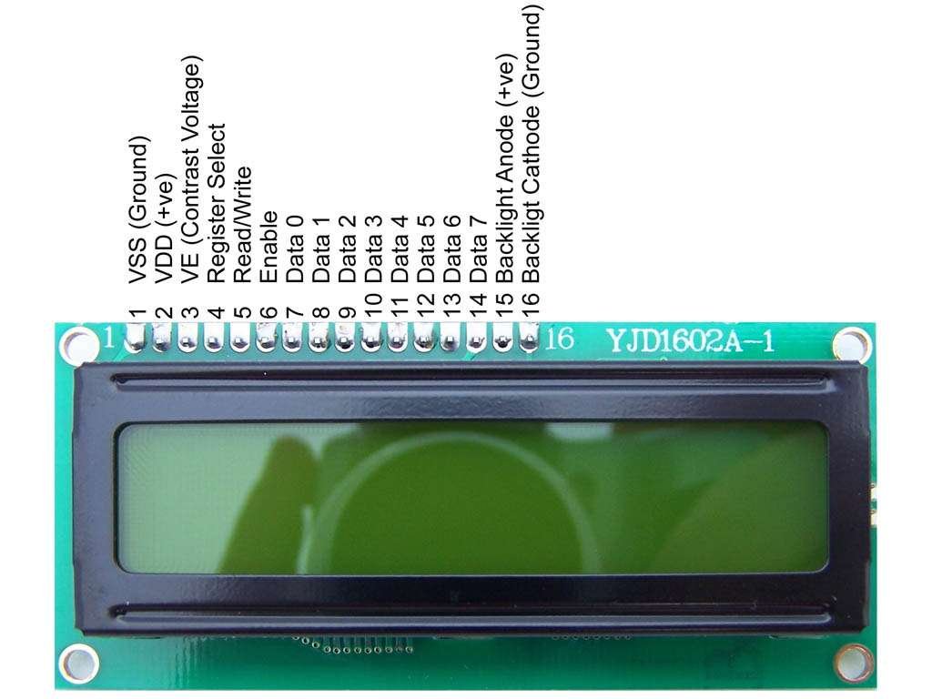
In this article we are going to use a 16×2 LCD driven by HD44780. This display usually comes with a monochromatic backlight and a 16 PIN header connector.
There are also some kits equipped with a 8-bit I/O expander for I2C bus which simplify connections and code but are costly. We will discuss this solution in another article.
The header PIN is organised as follows:
- VSS, connection to GND;
- VDD, power supply 2.7~5.5V DC;
- V0 or VE, contrast pad that should be connected to a potentiometer;
- RS, or Register Selector pad;
- RW, or Read Write selector pad;
- E, or Enable pad;
- D0, LSb parallel data pin;
- D1, data pin 1;
- D2, data pin 2;
- D3, data pin 3;
- D4, data pin 4;
- D5, data pin 5;
- D6, data pin 6;
- D7, MSb parallel data pin;
- A, backlight anode pin
- K, backlight cathode pin
Connecting the LCD to an STM32 Nucleo-64
In our case we have connected the LCD to an STM32 Nucleo-64. The first two PINs are required to power up the chip. Our connections are VSS to GND and VDD to 5V. The contrast regulator PIN (V0) has been connected to a 20k potentiometer which is between 3.3V and GND.
The backlight could be connected to 3.3V being normally on (A to 3.3V and K to GND) or it could be connected to a potentiometer allowing the dimmer. In our case we have decided to manage it through a PWM or through an output PIN. Our library allows software backlight management using a PWM or PAL (we suggest PWM tutorial as further reading). To do this K is connected to GND and A to a GPIO.
All the remaining PINs are connected to a GPIO. It is possible to select which GPIOs are used through software. Taking a look to the following code we can see how they are connected in our demo.
#define LINE_RS                     PAL_LINE(GPIOA, 4U)
#define LINE_RW                     PAL_LINE(GPIOA, 1U)
#define LINE_E                      PAL_LINE(GPIOA, 0U)
#define LINE_A                      PAL_LINE(GPIOA, 8U)

/* Data PIN are connected from PC0 to PC7 */
#if !LCD_USE_4_BIT_MODE
#define LINE_D0                     PAL_LINE(GPIOC, 0U)
#define LINE_D1                     PAL_LINE(GPIOC, 1U)
#define LINE_D2                     PAL_LINE(GPIOC, 2U)
#define LINE_D3                     PAL_LINE(GPIOC, 3U)
#endif
#define LINE_D4                     PAL_LINE(GPIOC, 4U)
#define LINE_D5                     PAL_LINE(GPIOC, 5U)
#define LINE_D6                     PAL_LINE(GPIOC, 6U)
#define LINE_D7                     PAL_LINE(GPIOC, 7U)
How it works
All the information about HD44780 working principle are extracted by the documentation previously introduce. We are going to summarise them in order to achieve our goal which is design a flexible library.
The communication interface uses a 8 + 3 or a 4 + 3 parallel bus. In both cases RW is used to select between reading or writing operation, RS is used to select the destination/source register and E is used to synchronise the communication.
Registers, DDRAM, GCRAM and GCROM
This controller has two 8-bit register: the instruction register (IR) and the data register (DR). The IR stores instructions. The DR temporarily stores data to be written into RAM.
When communicating with the HD44780 we can pull up RS to select the DR or pull down RS to select IR. This explains somehow this snippet of code we can find in the library:
/* LCD REGISTERS */
#define LCD_INSTRUCTION_R               PAL_LOW
#define LCD_DATA_R                      PAL_HIGH
The HD44780 has actually two RAM having two different purposes and one ROM: Data Display RAM (DDRAM), Character Generator RAM (CGRAM) and Character Generator ROM (CGROM).
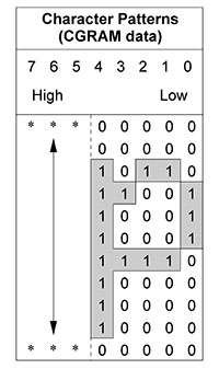
The CGROM contains a preset of characters which associate an 8-bit word to a pattern which actually is a bit matrix 5×8 or 5×10 representing the configuration of pixel required to draw that character on the LCD. The CGRAM could be used to edit these preset at run time.
For our purpose we are much more interested in DDRAM: HD44780 has typically a DDRAM which is enough big to address an 80 character display. Each DDRAM address indicate a block of memory required to represent a full character. In this way we have a correspondence one to one between DDRAM addresses and display “cells”.
In case of 2×16 display we should imagine DDRAM as wrapped in two lines. At start up the first top right character of the display is associated to address 0 of DDRAM and the bottom right character is associated to the address 40 of the DDRAM. Looking at figure 3 we can see we are now showing the whole DDRAM but only a small part (green cells).
According to the mounted CGROM there is an existing correspondance between character and ID. If our display as the European ROM, the set of characters are organised as the ASCII table. This means that if after the start up configuration we will write 65 in DDRAM @ position 0 we will see an ‘A’ in top right corner of our display.

Cursor and Display position
The cursor indicates the current address of DDRAM and thus where a character would be inserted in case of DDRAM write. It is possible to enable or disable it and also to make it blink. It could be shifted through the instruction Dsplay/Cursor shift.
The interesting part is that the display has a position as well. It could be shifted to using the same instruction to show another piece of DDRAM.
Interfacing the HD44780 to the STM32
To configure the HD44780 we need to read and write words which length is 8-bit. Each word could be an instruction as well as a data which must be stored in CGRAM or DDRAM. Sending instruction we can configure the device, writing data in DDRAM we can write on the display.
To do this the interface normally uses 8 lines (D) plus three lines required to handle the communication. If we need to read or write a word we have to set RS and RW as high or low in order to select the register and the direction of the communication.
If we want to read a word (RW high) we need to
- set D0 to D7 as input;
- pull up E;
- sample the logical status of Ds
- pull down E.
The logical status sampled from the data PINs represent the bit of our word where D0 is the less significant bit.
If we want to write a word (RW low) we need to
- set D0 to D7 as output push pull;
- pull up E;
- set the logical status of Ds according to the bit of our word;
- pull down E.
In our application we will often use this procedure and the following snippet code is a function internally used by our library to write a word named “value” into IR or DR according to “reg”.
Note that lcdp is a structure representing the LCDDriver which contains among other fields the PIN-map of our display which is obviously required by this function.
static void hd44780WriteRegister(LCDDriver *lcdp, uint8_t reg, uint8_t value){

  unsigned ii;

  while (hd44780IsBusy(lcdp))
    ;

  /* Configuring Data PINs as Output Push Pull. */
  for(ii = 0; ii < LINE_DATA_LEN; ii++)
    palSetLineMode(lcdp->config->pinmap->D[ii], PAL_MODE_OUTPUT_PUSHPULL |
                   PAL_STM32_OSPEED_HIGHEST);

  palClearLine(lcdp->config->pinmap->RW);
  palWriteLine(lcdp->config->pinmap->RS, reg);

#if LCD_USE_4_BIT_MODE
  for(ii = 0; ii < LINE_DATA_LEN; ii++) {
    if(value & (1 << (ii + 4)))
      palSetLine(lcdp->config->pinmap->D[ii]);
    else
      palClearLine(lcdp->config->pinmap->D[ii]);
  }
  palSetLine(lcdp->config->pinmap->E);
  osalThreadSleepMilliseconds(1);
  palClearLine(lcdp->config->pinmap->E);
  osalThreadSleepMilliseconds(1);

  for(ii = 0; ii < LINE_DATA_LEN; ii++) {
    if(value & (1 << ii))
      palSetLine(lcdp->config->pinmap->D[ii]);
    else
      palClearLine(lcdp->config->pinmap->D[ii]);
  }
  palSetLine(lcdp->config->pinmap->E);
  osalThreadSleepMilliseconds(1);
  palClearLine(lcdp->config->pinmap->E);
  osalThreadSleepMilliseconds(1);
#else
  for(ii = 0; ii < LINE_DATA_LEN; ii++){
      if(value & (1 << ii))
        palSetLine(lcdp->config->pinmap->D[ii]);
      else
        palClearLine(lcdp->config->pinmap->D[ii]);
  }
  palSetLine(lcdp->config->pinmap->E);
  osalThreadSleepMilliseconds(1);
  palClearLine(lcdp->config->pinmap->E);
  osalThreadSleepMilliseconds(1);
#endif
}
We should also notice that:
- In case of write, the HD44780 sample the status of data PIN when E shift from high to low so we can also set the logical status of Ds before to set E as high.
- Before to write we are waiting until the display is not busy. The busy flag could be retrieved through a read operation and is high when the device is performing some internal operation: in this case we cannot write into the registers.
- This function is compatible also with 4-bit mode. The HD44780 could be addressed using only 4 data PINs (D4 to D7). In this case two transfers are required to send a whole word as shown in figure 4.
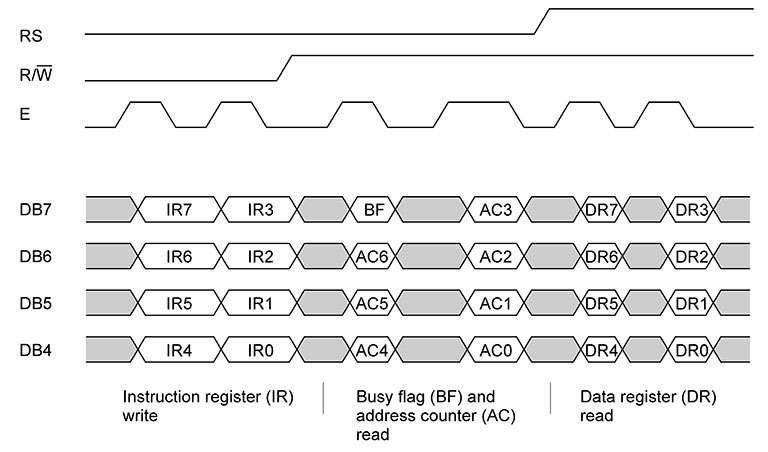
The communication scheme for the HD44780 in 4 bit mode.
Instructions
The interface provide a small set of instruction to configure the chip, check the busy flag and read or write into the RAM.
The instruction to configure the chip are 8, 1 instruction is to check the busy flag and the address counter (which we are almost ignoring in our implementation) and 2 instructions to read and write into DDRAM or CGRAM totalling 11 instructions.
Write instructions
The instruction to configure the chip are write only and the register destination is the Instruction Register (IR) so they always requires RS and RW to 0. The instruction type is identified by the most significant 1 and they are
| Instruction | D7 | D6 | D5 | D4 | D3 | D2 | D1 | D0 |
| Clear display | 0 | 0 | 0 | 0 | 0 | 0 | 0 | 1 |
|---|---|---|---|---|---|---|---|---|
| Return home | 0 | 0 | 0 | 0 | 0 | 0 | 1 | – |
| Entry mode set | 0 | 0 | 0 | 0 | 0 | 1 | I/D | S |
| Display control | 0 | 0 | 0 | 0 | 1 | D | C | B |
| Cursor/Display shift | 0 | 0 | 0 | 1 | S/C | R/L | – | – |
| Function set | 0 | 0 | 1 | DL | N | F | – | – |
| Set CGRAM address | 0 | 1 | ACG | ACG | ACG | ACG | ACG | ACG |
| Set DDRAM address | 1 | ADD | ADD | ADD | ADD | ADD | ADD | ADD |
These instruction are internally used by our library and not all of them are exposed to user through the API because certain instructions, like “Function set”, must be used in a specific context we will explain later.
Clear display: clear the DDRAM and set the current address of DDRAM to 0. It set also the display position and the cursor position to 0. This command is exported through the API lcdClearDisplay().
Return home: perform the same operation of Clear Display without clear the DDRAM content so the text on the display will be untouched after this command. This command is exported through the API lcdReturnHome().
Entry set mode: specify what happens to the current DDRAM address when we push a value into this memory: it Increments (I/D = 1) or Decrements (I/D = 0). It specifies also if the display shifts to each push (S = 1). In our library this value is not configurable and we always set I/D = 1 and S = 0.
Display control: it allow to set the entire display on (D = 1) or off (D = 0), cursor on/off (C), and blinking of cursor position character (B). In our library user can act on cursor and blinking through the display configuration structure.
Cursor/Display shift: allow to shift of one position the Display (S/C = 1) or the Cursor (S/C = 0). In our library this instruction is partially exposed through the API lcdDoDisplayShift().
Function set: it allow to set the interface mode in 8-bit mode (DL = 1) or 4-bit mode (DL = 0), the number of lines to 2 (N = 1) or 1 (N = 0) and the font type size to 5 × 10 dots (F = 1) or 5 × 8 dots (F = 0). Note that this instruction must be sent in the initialization phase which strictly depends on DL. In our library data length is selectable by a preprocessor switch named LCD_USE_4_BIT_MODE, number of lines and font type is selectable in the display configuration structure.
Set CGRAM address: allow to set the CGRAM address. In our library this instruction is not used.
Set DDRAM address: allow to set the DDRAM address. In our library this instruction is exposed through the API lcdSetAddress() and internally used by the API lcdWriteString().
Note that to write data in CGRAM and DDRAM the procedure is to set the address in the Instruction Register (IR) and then to write the data in the Data Register (DR). The operation will be completed internally. As example if we want to push ’65’ in the DDRAM @ position 6 we need to do a Set DDRAM address (RS = 0, RW = 0, D = 10000110) and then push data into the DR (RS = 1, RW = 0, D = 01000001).
If we want to write more than a data in adjacent memory spaces, we need to set the address only the first time then the internal circuitry will increase or decrease current memory address according to the Entry mode Set which is always set as incremental in our library.
This instruction is internally used by the API lcdWriteString() to write data in the DDRAM.
Read instructions
In a similar way we can read data from the RAM (RS = 1, RW = 1). The data captured will be the content of the current address of the latest selected RAM. This instruction is never implemented in our library because we don’t need of it.
Reading from the Instruction Register (RS = 0, RW = 1) we will get the Busy Flag (D7) and the Address Counter (D6~D0) which is the current address of the DDRAM or CGRAM. We almost ignore the AC but we use this instruction to check the status of busy flag before to issue a new instruction. The function which check the busy flag is used internally and is:
static bool hd44780IsBusy(LCDDriver *lcdp) {
 bool busy;
 unsigned ii;

 /* Configuring Data PINs as Input. */
 for(ii = 0; ii < LINE_DATA_LEN; ii++)
 palSetLineMode(lcdp->config->pinmap->D[ii], PAL_MODE_INPUT);

 palSetLine(lcdp->config->pinmap->RW);
 palClearLine(lcdp->config->pinmap->RS);

 palSetLine(lcdp->config->pinmap->E);
 osalThreadSleepMilliseconds(1);
 busy = (palReadLine(lcdp->config->pinmap->D[LINE_DATA_LEN - 1]) == PAL_HIGH);
 palClearLine(lcdp->config->pinmap->E);
 osalThreadSleepMilliseconds(1);

#if LCD_USE_4_BIT_MODE
 palSetLine(lcdp->config->pinmap->E);
 osalThreadSleepMilliseconds(1);
 palClearLine(lcdp->config->pinmap->E);
 osalThreadSleepMilliseconds(1);
#endif
 return busy;
}
Initializing the device
On start up an internal circuit perform an initialisation which lead the HD44780 in a know status. If the device is not powered properly or if it has been misconfigured it could happen that this initialization doesn’t occurs. In that case there is a procedure of initialization by instruction which is different if we want to use 8-bit or 4-bit mode. Note that if we would change the operation mode a re-initialization is required.
This initialization actually is a sequence of write performed by this function used internally by our library:
static void hd44780InitByIstructions(LCDDriver *lcdp) {
  unsigned ii;

  osalThreadSleepMilliseconds(50);
  for(ii = 0; ii < LINE_DATA_LEN; ii++) {
    palSetLineMode(lcdp->config->pinmap->D[ii], PAL_MODE_OUTPUT_PUSHPULL |
                   PAL_STM32_OSPEED_HIGHEST);
    palClearLine(lcdp->config->pinmap->D[ii]);
  }

  palClearLine(lcdp->config->pinmap->E);
  palClearLine(lcdp->config->pinmap->RW);
  palClearLine(lcdp->config->pinmap->RS);
  palSetLine(lcdp->config->pinmap->D[LINE_DATA_LEN - 3]);
  palSetLine(lcdp->config->pinmap->D[LINE_DATA_LEN - 4]);

  palSetLine(lcdp->config->pinmap->E);
  osalThreadSleepMilliseconds(1);
  palClearLine(lcdp->config->pinmap->E);
  osalThreadSleepMilliseconds(5);

  palSetLine(lcdp->config->pinmap->E);
  osalThreadSleepMilliseconds(1);
  palClearLine(lcdp->config->pinmap->E);
  osalThreadSleepMilliseconds(1);

  palSetLine(lcdp->config->pinmap->E);
  osalThreadSleepMilliseconds(1);
  palClearLine(lcdp->config->pinmap->E);

#if LCD_USE_4_BIT_MODE
  palSetLine(lcdp->config->pinmap->D[LINE_DATA_LEN - 3]);
  palClearLine(lcdp->config->pinmap->D[LINE_DATA_LEN - 4]);
  palSetLine(lcdp->config->pinmap->E);
  osalThreadSleepMilliseconds(1);
  palClearLine(lcdp->config->pinmap->E);
#endif

  /* Configuring data interface */
  hd44780WriteRegister(lcdp, LCD_INSTRUCTION_R, LCD_FS | LCD_DATA_LENGHT |
                       lcdp->config->font | lcdp->config->lines);

  /* Turning off display and clearing */
  hd44780WriteRegister(lcdp, LCD_INSTRUCTION_R, LCD_DC);
  hd44780WriteRegister(lcdp, LCD_INSTRUCTION_R, LCD_CLEAR_DISPLAY);

  /* Setting display control turning on display */
  hd44780WriteRegister(lcdp, LCD_INSTRUCTION_R, LCD_DC | LCD_DC_D |
                       lcdp->config->cursor | lcdp->config->blinking);

  /* Setting Entry Mode */
  hd44780WriteRegister(lcdp, LCD_INSTRUCTION_R, LCD_EMS | LCD_EMS_ID);
}
Note that the latest five instructions are still part of the initialization but depends strictly on user configuration which is stored in the LCDDriver structure and lcdp is a pointer to it.
LCDDriver and LCDConfig
Our library has been created emulating the the design of ChibiOS/HAL. The driver is an object which implements a state machine shown in the next figure:
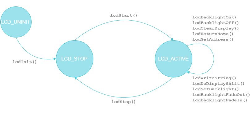
The LCDDriver contains the current state, the current backlight percentage and a pointer to the current configuration. This configuration is defined by user and used in lcdStart().
The configuration allow to enable/disable cursor and blinking, to choose font type and the number of lines. It contains also the PIN-map of the LCD and backlight related fields.
As example whats follow is the configuration used in our presented demo and its dependencies:
#define LINE_RS                     PAL_LINE(GPIOA, 4U)
#define LINE_RW                     PAL_LINE(GPIOA, 1U)
#define LINE_E                      PAL_LINE(GPIOA, 0U)
#define LINE_A                      PAL_LINE(GPIOA, 8U)

/* Data PIN are connected from PC0 to PC7 */
#if !LCD_USE_4_BIT_MODE
#define LINE_D0                     PAL_LINE(GPIOC, 0U)
#define LINE_D1                     PAL_LINE(GPIOC, 1U)
#define LINE_D2                     PAL_LINE(GPIOC, 2U)
#define LINE_D3                     PAL_LINE(GPIOC, 3U)
#endif
#define LINE_D4                     PAL_LINE(GPIOC, 4U)
#define LINE_D5                     PAL_LINE(GPIOC, 5U)
#define LINE_D6                     PAL_LINE(GPIOC, 6U)
#define LINE_D7                     PAL_LINE(GPIOC, 7U)

/*===========================================================================*/
/* LCD configuration                                                         */
/*===========================================================================*/

#if LCD_USE_DIMMABLE_BACKLIGHT
static const PWMConfig pwmcfg = {
  100000,                                   /* 100kHz PWM clock frequency.   */
  100,                                      /* PWM period is 1000 cycles.    */
  NULL,
  {
   {PWM_OUTPUT_ACTIVE_HIGH, NULL},
   {PWM_OUTPUT_DISABLED, NULL},
   {PWM_OUTPUT_DISABLED, NULL},
   {PWM_OUTPUT_DISABLED, NULL}
  },
  0,
  0
};
#endif

static const lcd_pins_t lcdpins = {
  LINE_RS,
  LINE_RW,
  LINE_E,
  LINE_A,
  {
#if !LCD_USE_4_BIT_MODE
   LINE_D0,
   LINE_D1,
   LINE_D2,
   LINE_D3,
#endif
   LINE_D4,
   LINE_D5,
   LINE_D6,
   LINE_D7
  }
};

static const LCDConfig lcdcfg = {
  LCD_CURSOR_OFF,           /* Cursor disabled */
  LCD_BLINKING_OFF,         /* Blinking disabled */
  LCD_SET_FONT_5X10,        /* Font 5x10 */
  LCD_SET_2LINES,           /* 2 lines */
  &lcdpins,                 /* pin map */
#if LCD_USE_DIMMABLE_BACKLIGHT
  &PWMD1,                   /* PWM Driver for back-light */
  &pwmcfg,                  /* PWM driver configuration for back-light */
  0,                        /* PWM channel */
#endif
  100,                      /* Back-light */
};
Note that the PIN-map of the LCD depends on the used interface. It is basically a structure and one of its field is an array of lines which length depends on LCD_USE_4_BIT_MODE: this array indeed represent the D pins which are 4 instead of 8 in 4-bit mode.
It is also important to note that configuration structure has three additional fields when LCD_USE_DIMMABLE_BACKLIGHT is enabled. These fields are a PWM driver , its configuration and the channel which is connected to the LCD backlight. When this option is disabled the backlight percentage is considered a boolean (e.g. the display back light is on when this value is not zero).
5 API explained
The API of our library exposes a set of function which receives as first parameter a pointer to a LCDDriver (except lcdInit()).
lcdInit()
This function must be invoked before to use any of all the exposed functions, it requires void and return void. Note that it act on objects and there is no initialization of hardware on this function. After the execution of it the driver goes in the LCD_STOP state.
lcdStart()
This function configure the hardware to be ready to use. It requires the pointer to the driver and a pointer to the configuration which is user defined. After the execution of it the driver goes in the LCD_ACTIVE state.
lcdStop()
This function reset the hardware stopping it. It requires the pointer to the driver only. After the execution of it the driver goes int the LCD_STOP state.
lcdBacklightOn()
It set backlight percentage to 100. It doesn’t requires LCD_USE_DIMMABLE_BACKLIGHT. It requires the pointer to the driver only and after the execution of it the driver remains in the LCD_ACTIVE state.
lcdBacklightOff()
It set backlight percentage to 0. It doesn’t requires LCD_USE_DIMMABLE_BACKLIGHT. It requires the pointer to the driver only and after the execution of it the driver remains in the LCD_ACTIVE state.
lcdClearDisplay()
This function execute the Clear Display: clear the DDRAM and set the current address of DDRAM to 0. It set also the display position and the cursor position to 0. It requires the pointer to the driver only and after the execution of it the driver remains in the LCD_ACTIVE state.
lcdReturnHome()
This function execute the Return home: perform the same operation of Clear Display without clear the DDRAM content so the text on the display will be untouched after this command. It requires the pointer to the driver only and after the execution of it the driver remains in the LCD_ACTIVE state.
lcdSetAddress()
This function execute the Set DDRAM address. It requires the pointer to the driver and the DDRAM address. After the execution of it the driver remains in the LCD_ACTIVE state.
lcdWriteString()
This function set the DDRAM address and pushes a string in it. Requires the pointer to the driver, the string and the starting DDRAM address. After the execution of it the driver remains in the LCD_ACTIVE state.
lcdDoDisplayShift
This function perform a Shift of the display. Requires the pointer to the driver, and the direction of the shift which could be LCD_RIGHT or LCD_LEFT. After the execution of it the driver remains in the LCD_ACTIVE state.
lcdSetBacklight()
This function set the LCD percentage to a value in a range from 0 an 100. Requires the pointer to the driver, and the percentage value. After the execution of it the driver remains in the LCD_ACTIVE state. This API is available only if LCD_USE_DIMMABLE_BACKLIGHT.
lcdBacklightFadeOut()
This function gradually shift the backlight percentage to 0 creating a smooth effect. Requires the pointer to the driver only. After the execution of it the driver remains in the LCD_ACTIVE state. This API is available only if LCD_USE_DIMMABLE_BACKLIGHT.
lcdBacklightFadeIn()
This function gradually shift the backlight percentage to 100 creating a smooth effect. Requires the pointer to the driver only. After the execution of it the driver remains in the LCD_ACTIVE state. This API is available only if LCD_USE_DIMMABLE_BACKLIGHT.
A simple demo
Our test application is a simple demo which shows how to use the library. Since the library uses OSAL it could be used on both RT and NIL and eventually on other RTOSes also.
We have created two demos which do the same thing using ChibiOS/RT and ChibiOS/NIL over an STM32 Nucleo-64 F401RE but it would be quite easy to port this application on another platform supported by ChibiOS/HAL.
The application uses three threads: one is a classical LED blinker, one is a backlight manager and the last one manage display.
#include "ch.h"
#include "hal.h"

#include "lcd.h"

static uint8_t ii;

#define LINE_RS                     PAL_LINE(GPIOA, 4U)
#define LINE_RW                     PAL_LINE(GPIOA, 1U)
#define LINE_E                      PAL_LINE(GPIOA, 0U)
#define LINE_A                      PAL_LINE(GPIOA, 8U)

/* Data PIN are connected from PC0 to PC7 */
#if !LCD_USE_4_BIT_MODE
#define LINE_D0                     PAL_LINE(GPIOC, 0U)
#define LINE_D1                     PAL_LINE(GPIOC, 1U)
#define LINE_D2                     PAL_LINE(GPIOC, 2U)
#define LINE_D3                     PAL_LINE(GPIOC, 3U)
#endif
#define LINE_D4                     PAL_LINE(GPIOC, 4U)
#define LINE_D5                     PAL_LINE(GPIOC, 5U)
#define LINE_D6                     PAL_LINE(GPIOC, 6U)
#define LINE_D7                     PAL_LINE(GPIOC, 7U)

/*===========================================================================*/
/* LCD configuration                                                         */
/*===========================================================================*/

#if LCD_USE_DIMMABLE_BACKLIGHT
static const PWMConfig pwmcfg = {
  100000,                                   /* 100kHz PWM clock frequency.   */
  100,                                      /* PWM period is 1000 cycles.    */
  NULL,
  {
   {PWM_OUTPUT_ACTIVE_HIGH, NULL},
   {PWM_OUTPUT_DISABLED, NULL},
   {PWM_OUTPUT_DISABLED, NULL},
   {PWM_OUTPUT_DISABLED, NULL}
  },
  0,
  0
};
#endif

static const lcd_pins_t lcdpins = {
  LINE_RS,
  LINE_RW,
  LINE_E,
  LINE_A,
  {
#if !LCD_USE_4_BIT_MODE
   LINE_D0,
   LINE_D1,
   LINE_D2,
   LINE_D3,
#endif
   LINE_D4,
   LINE_D5,
   LINE_D6,
   LINE_D7
  }
};

static const LCDConfig lcdcfg = {
  LCD_CURSOR_OFF,           /* Cursor disabled */
  LCD_BLINKING_OFF,         /* Blinking disabled */
  LCD_SET_FONT_5X10,        /* Font 5x10 */
  LCD_SET_2LINES,           /* 2 lines */
  &lcdpins,                 /* pin map */
#if LCD_USE_DIMMABLE_BACKLIGHT
  &PWMD1,                   /* PWM Driver for back-light */
  &pwmcfg,                  /* PWM driver configuration for back-light */
  0,                        /* PWM channel */
#endif
  100,                      /* Back-light */
};

/*
 * Green LED blinker thread, times are in milliseconds.
 */
static THD_WORKING_AREA(waThread1, 128);
static THD_FUNCTION(Thread1, arg) {

  (void)arg;
  chRegSetThreadName("LED blinker");
  while (true) {
    palClearPad(GPIOA, GPIOA_LED_GREEN);
    chThdSleepMilliseconds(500);
    palSetPad(GPIOA, GPIOA_LED_GREEN);
    chThdSleepMilliseconds(500);
  }
}

/*
 * Button checker. This thread turn on and off LCD backlight when USER button
 * is pressed. Fade transition is applied when library use PWM.
 */
static THD_WORKING_AREA(waThread2, 128);
static THD_FUNCTION(Thread2, arg) {

  (void)arg;
  chRegSetThreadName("Back_light handler");
  while (true) {
    if(palReadPad(GPIOC, GPIOC_BUTTON)){
      chThdSleepMilliseconds(50);
      if(!palReadPad(GPIOC, GPIOC_BUTTON)){
        if(LCDD1.backlight > 0) {
#if LCD_USE_DIMMABLE_BACKLIGHT
          lcdBacklightFadeOut(&LCDD1);
#else
          lcdBacklightOff(&LCDD1);
#endif
        }
        else {
#if LCD_USE_DIMMABLE_BACKLIGHT
          lcdBacklightFadeIn(&LCDD1);
#else
          lcdBacklightOn(&LCDD1);
#endif
        }
      }
    }
    chThdSleepMilliseconds(10);
  }
}

/*
 * Application entry point.
 */
int main(void) {

  /*
   * System initializations.
   * - HAL initialization, this also initializes the configured device drivers
   *   and performs the board-specific initializations.
   * - Kernel initialization, the main() function becomes a thread and the
   *   RTOS is active.
   */
  halInit();
  chSysInit();


  lcdInit();

  /* Creating blinker thread and backlight thread. */
  chThdCreateStatic(waThread1, sizeof(waThread1), NORMALPRIO, Thread1, NULL);
  chThdCreateStatic(waThread2, sizeof(waThread2), NORMALPRIO, Thread2, NULL);

#if LCD_USE_DIMMABLE_BACKLIGHT
  /* Configuring Anode PIN as TIM1 CH1 alternate function. */
  palSetLineMode(LINE_A, PAL_MODE_ALTERNATE(1));
#else
  /* Configuring Anode PIN as TIM1 CH1 alternate function. */
  palSetLineMode(LINE_A, PAL_MODE_OUTPUT_PUSHPULL |
                 PAL_STM32_OSPEED_HIGHEST);
#endif


  /* Configuring RW, RS and E PIN as Output Push Pull. Note that Data PIN are
     managed Internally */
  palSetLineMode(LINE_RW, PAL_MODE_OUTPUT_PUSHPULL |
                PAL_STM32_OSPEED_HIGHEST);
  palSetLineMode(LINE_RS, PAL_MODE_OUTPUT_PUSHPULL |
                PAL_STM32_OSPEED_HIGHEST);
  palSetLineMode(LINE_E, PAL_MODE_OUTPUT_PUSHPULL |
                PAL_STM32_OSPEED_HIGHEST);


  lcdStart(&LCDD1, &lcdcfg);
  lcdWriteString(&LCDD1, "PLAY            Learn", 0);
  lcdWriteString(&LCDD1, "Embedded        by doing",40);
  chThdSleepMilliseconds(2000);
  while (true) {
    for(ii = 0; ii < 16; ii++){
      lcdDoDisplayShift(&LCDD1, LCD_LEFT);
      chThdSleepMilliseconds(50);
    }
    chThdSleepMilliseconds(2000);
    for(ii = 0; ii < 16; ii++){
      lcdDoDisplayShift(&LCDD1, LCD_RIGHT);
      chThdSleepMilliseconds(50);
    }
    chThdSleepMilliseconds(2000);
  }
}
The backlight thread just check if the user button as been pressed and toggles the status of back-light using fading when LCD_USE_DIMMABLE_BACKLIGHT.
The display thread, which actually is the main, starts the LCD with the user defined configuration, writes a string for each line of the display and continuously perform shift creating a simple animation on the display.
Project download
The attached demo has been tested under ChibiOS 20.3.x.
Be the first to reply at How to use an HD44780 based Liquid Crystal Display