How to leverage Board Files in ChibiOS
Introduction
The board files are a critical component of a ChibiOS-based project. They define how peripherals are connected to the microcontroller and provide information related to key elements that depend on the board in use. This article will discuss what board files are in ChibiOS, their role in a project, and how to generate customized ones.
Board files explained
Board files are platform-dependent source files that handle low-level functionality. They provide some board-specific configurations, the pin and line identifiers and they initialize the whole GPIO memory bank before the user application starts.
Board-specific configurations
Microcontrollers are very flexible and they can work with different levels of voltage as well as different clock sources (internal and external). However to work properly the clock tree and the power management unit needs to be appropriately configured. Some boards can be equipped with special physical layers (PHY) to implement communication stacks such as the USB Low Power Interface (ULPI) or the Ethernet PHY. To work properly, ChibiOS/HAL needs to be aware of these board-dependent configurations and these are provided in the board files.
For instance, the opening code of the SDP-K1 board header file shows the initial definitions related to the low-speed and high-speed external clocks (STM32_LSECLK and STM32_HSECLK), followed by the specification of the MCU voltage and type. These values are internally used to calculate the clock-tree speed and power management limits and ensure that the absolute maximum values specified in the datasheet are not exceeded.
/*
 * Board identifier.
 */
#define BOARD_ADI_EVAL_SDP_CK1Z
#define BOARD_NAME                  "Analog Devices SDP-CK1Z"

/*
 * The board has an ULPI USB PHY.
 */
#define BOARD_OTG2_USES_ULPI

/*
 * Board oscillators-related settings.
 */
#if !defined(STM32_LSECLK)
#define STM32_LSECLK                32768U
#endif

#if !defined(STM32_HSECLK)
#define STM32_HSECLK                8000000U
#endif

/*
 * Board voltages.
 * Required for performance limits calculation.
 */
#define STM32_VDD                   300U

/*
 * MCU type as defined in the ST header.
 */
#define STM32F469xx
IO pin assignments
GPIOs are organized in banks, requiring the use of both a bank identifier (often referred to as Port) and a pin number (often referred to as Pad) to identify a pin. For example, STM32 uses letters for ports (GPIOA, GPIOB, GPIOC, etc.) and numbers for pads (0 to 15), while Atmel SAM still uses letters for ports and numbers for pads but with wider banks (0 to 32).
In ChibiOS, board files offer user-friendly aliases for each Pad, improving code readability and usability. The following shows an example of IO pins assignments in the SDP-K1 board file. Note that not all aliases are custom, and some are assigned by default (e.g. GPIOB_PIN14). Additionally, multiple aliases can be assigned to the same pin.
/*
 * IO pins assignments.
 */
#define GPIOA_ARD_D1                0U
#define GPIOA_ARD_D0                1U
#define GPIOA_ARD_A0                2U
#define GPIOA_ULPI_D0               3U
#define GPIOA_ARD_A1                4U
#define GPIOA_ULPI_CK               5U
#define GPIOA_ARD_A2                6U
#define GPIOA_ARD_D11               7U
#define GPIOA_PIN8                  8U
#define GPIOA_PIN9                  9U
#define GPIOA_ARD_D6                10U
#define GPIOA_ARD_D5                11U
#define GPIOA_PIN12                 12U
#define GPIOA_SWDIO                 13U
#define GPIOA_SWCLK                 14U
#define GPIOA_ARD_D10               15U

#define GPIOB_ULPI_D1               0U
#define GPIOB_ULPI_D2               1U
#define GPIOB_PIN2                  2U
#define GPIOB_ARD_D13               3U
#define GPIOB_ARD_D12               4U
#define GPIOB_ULPI_D7               5U
#define GPIOB_PIN6                  6U
#define GPIOB_ARD_D14               7U
#define GPIOB_ARD_D15               8U
#define GPIOB_PIN9                  9U
#define GPIOB_ULPI_D3               10U
#define GPIOB_ULPI_D4               11U
#define GPIOB_ULPI_D5               12U
#define GPIOB_ULPI_D6               13U
#define GPIOB_PIN14                 14U
#define GPIOB_ARD_D9                15U

#define GPIOC_ULPI_STP              0U
#define GPIOC_ARD_A3                1U
#define GPIOC_ULPI_DIR              2U
#define GPIOC_ULPI_NXT              3U
#define GPIOC_ARD_A4                4U
#define GPIOC_ARD_A5                5U
#define GPIOC_PIN6                  6U
#define GPIOC_PIN7                  7U
#define GPIOC_PIN8                  8U
#define GPIOC_PIN9                  9U
#define GPIOC_PIN10                 10U
#define GPIOC_PIN11                 11U
#define GPIOC_DAP_VCP_RX            12U
#define GPIOC_PIN13                 13U
#define GPIOC_PIN14                 14U
#define GPIOC_PIN15                 15U

#define GPIOD_PIN0                  0U
#define GPIOD_PIN1                  1U
#define GPIOD_DAP_VCP_TX            2U
#define GPIOD_PIN3                  3U
#define GPIOD_PIN4                  4U
#define GPIOD_PIN5                  5U
#define GPIOD_PIN6                  6U
#define GPIOD_USB_RESET             7U
#define GPIOD_PIN8                  8U
#define GPIOD_PIN9                  9U
#define GPIOD_PIN10                 10U
#define GPIOD_PIN11                 11U
#define GPIOD_ARD_D3                12U
#define GPIOD_PIN13                 13U
#define GPIOD_PIN14                 14U
#define GPIOD_PIN15                 15U

#define GPIOE_PIN0                  0U
#define GPIOE_PIN1                  1U
#define GPIOE_PIN2                  2U
#define GPIOE_PIN3                  3U
#define GPIOE_PIN4                  4U
#define GPIOE_PIN5                  5U
#define GPIOE_PIN6                  6U
#define GPIOE_PIN7                  7U
#define GPIOE_PIN8                  8U
#define GPIOE_PIN9                  9U
#define GPIOE_PIN10                 10U
#define GPIOE_PIN11                 11U
#define GPIOE_PIN12                 12U
#define GPIOE_PIN13                 13U
#define GPIOE_PIN14                 14U
#define GPIOE_PIN15                 15U

#define GPIOF_PIN0                  0U
#define GPIOF_PIN1                  1U
#define GPIOF_PIN2                  2U
#define GPIOF_PIN3                  3U
#define GPIOF_PIN4                  4U
#define GPIOF_PIN5                  5U
#define GPIOF_PIN6                  6U
#define GPIOF_PIN7                  7U
#define GPIOF_PIN8                  8U
#define GPIOF_PIN9                  9U
#define GPIOF_PIN10                 10U
#define GPIOF_PIN11                 11U
#define GPIOF_PIN12                 12U
#define GPIOF_PIN13                 13U
#define GPIOF_PIN14                 14U
#define GPIOF_PIN15                 15U

#define GPIOG_PIN0                  0U
#define GPIOG_PIN1                  1U
#define GPIOG_PIN2                  2U
#define GPIOG_PIN3                  3U
#define GPIOG_PIN4                  4U
#define GPIOG_PIN5                  5U
#define GPIOG_PIN6                  6U
#define GPIOG_ARD_D2                7U
#define GPIOG_PIN8                  8U
#define GPIOG_ARD_D4                9U
#define GPIOG_ARD_D7                10U
#define GPIOG_ARD_D8                11U
#define GPIOG_PIN12                 12U
#define GPIOG_PIN13                 13U
#define GPIOG_PIN14                 14U
#define GPIOG_PIN15                 15U

#define GPIOH_OSC_IN                0U
#define GPIOH_OSC_OUT               1U
#define GPIOH_PIN2                  2U
#define GPIOH_PIN3                  3U
#define GPIOH_PIN4                  4U
#define GPIOH_PIN5                  5U
#define GPIOH_PIN6                  6U
#define GPIOH_PIN7                  7U
#define GPIOH_PIN8                  8U
#define GPIOH_PIN9                  9U
#define GPIOH_PIN10                 10U
#define GPIOH_PIN11                 11U
#define GPIOH_PIN12                 12U
#define GPIOH_PIN13                 13U
#define GPIOH_PIN14                 14U
#define GPIOH_PIN15                 15U

#define GPIOI_PIN0                  0U
#define GPIOI_PIN1                  1U
#define GPIOI_PIN2                  2U
#define GPIOI_PIN3                  3U
#define GPIOI_PIN4                  4U
#define GPIOI_PIN5                  5U
#define GPIOI_PIN6                  6U
#define GPIOI_PIN7                  7U
#define GPIOI_PIN8                  8U
#define GPIOI_PIN9                  9U
#define GPIOI_PIN10                 10U
#define GPIOI_PIN11                 11U
#define GPIOI_PIN12                 12U
#define GPIOI_PIN13                 13U
#define GPIOI_PIN14                 14U
#define GPIOI_PIN15                 15U

#define GPIOJ_PIN0                  0U
#define GPIOJ_PIN1                  1U
#define GPIOJ_PIN2                  2U
#define GPIOJ_PIN3                  3U
#define GPIOJ_PIN4                  4U
#define GPIOJ_PIN5                  5U
#define GPIOJ_PIN6                  6U
#define GPIOJ_PIN7                  7U
#define GPIOJ_PIN8                  8U
#define GPIOJ_PIN9                  9U
#define GPIOJ_PIN10                 10U
#define GPIOJ_PIN11                 11U
#define GPIOJ_PIN12                 12U
#define GPIOJ_PIN13                 13U
#define GPIOJ_PIN14                 14U
#define GPIOJ_PIN15                 15U

#define GPIOK_PIN0                  0U
#define GPIOK_PIN1                  1U
#define GPIOK_PIN2                  2U
#define GPIOK_PIN3                  3U
#define GPIOK_PROCESSOR_STATUS      4U
#define GPIOK_LED_GREEN             5U
#define GPIOK_LED_ORANGE            6U
#define GPIOK_LED_RED               7U
#define GPIOK_PIN8                  8U
#define GPIOK_PIN9                  9U
#define GPIOK_PIN10                 10U
#define GPIOK_PIN11                 11U
#define GPIOK_PIN12                 12U
#define GPIOK_PIN13                 13U
#define GPIOK_PIN14                 14U
#define GPIOK_PIN15                 15U
The following instruction is a PAL API that sets a digital output line high. In this specific case, we are setting high the pin PK5 of the SDP-K1.
palSetPad(GPIOK, 5U);
In reality, this pin is connected to the green LED of the SDP-K1. To make the call more user-friendly, we can leverage the board files definitions and use the symbolic alias for PK5 named GPIOK_LED_GREEN.
palSetPad(GPIOK, GPIOK_LED_GREEN);
In some architectures, a single identifier, called Line, can convey both the Port and Pad values. The board files offer a list of Line identifiers for all pins that have a custom alias defined.
/*
 * IO lines assignments.
 */
#define LINE_ARD_D1                 PAL_LINE(GPIOA, 0U)
#define LINE_ARD_D0                 PAL_LINE(GPIOA, 1U)
#define LINE_ARD_A0                 PAL_LINE(GPIOA, 2U)
#define LINE_ULPI_D0                PAL_LINE(GPIOA, 3U)
#define LINE_ARD_A1                 PAL_LINE(GPIOA, 4U)
#define LINE_ULPI_CK                PAL_LINE(GPIOA, 5U)
#define LINE_ARD_A2                 PAL_LINE(GPIOA, 6U)
#define LINE_ARD_D11                PAL_LINE(GPIOA, 7U)
#define LINE_ARD_D6                 PAL_LINE(GPIOA, 10U)
#define LINE_ARD_D5                 PAL_LINE(GPIOA, 11U)
#define LINE_SWDIO                  PAL_LINE(GPIOA, 13U)
#define LINE_SWCLK                  PAL_LINE(GPIOA, 14U)
#define LINE_ARD_D10                PAL_LINE(GPIOA, 15U)
#define LINE_ULPI_D1                PAL_LINE(GPIOB, 0U)
#define LINE_ULPI_D2                PAL_LINE(GPIOB, 1U)
#define LINE_ARD_D13                PAL_LINE(GPIOB, 3U)
#define LINE_ARD_D12                PAL_LINE(GPIOB, 4U)
#define LINE_ULPI_D7                PAL_LINE(GPIOB, 5U)
#define LINE_ARD_D14                PAL_LINE(GPIOB, 7U)
#define LINE_ARD_D15                PAL_LINE(GPIOB, 8U)
#define LINE_ULPI_D3                PAL_LINE(GPIOB, 10U)
#define LINE_ULPI_D4                PAL_LINE(GPIOB, 11U)
#define LINE_ULPI_D5                PAL_LINE(GPIOB, 12U)
#define LINE_ULPI_D6                PAL_LINE(GPIOB, 13U)
#define LINE_ARD_D9                 PAL_LINE(GPIOB, 15U)
#define LINE_ULPI_STP               PAL_LINE(GPIOC, 0U)
#define LINE_ARD_A3                 PAL_LINE(GPIOC, 1U)
#define LINE_ULPI_DIR               PAL_LINE(GPIOC, 2U)
#define LINE_ULPI_NXT               PAL_LINE(GPIOC, 3U)
#define LINE_ARD_A4                 PAL_LINE(GPIOC, 4U)
#define LINE_ARD_A5                 PAL_LINE(GPIOC, 5U)
#define LINE_DAP_VCP_RX             PAL_LINE(GPIOC, 12U)
#define LINE_DAP_VCP_TX             PAL_LINE(GPIOD, 2U)
#define LINE_USB_RESET              PAL_LINE(GPIOD, 7U)
#define LINE_ARD_D3                 PAL_LINE(GPIOD, 12U)
#define LINE_ARD_D2                 PAL_LINE(GPIOG, 7U)
#define LINE_ARD_D4                 PAL_LINE(GPIOG, 9U)
#define LINE_ARD_D7                 PAL_LINE(GPIOG, 10U)
#define LINE_ARD_D8                 PAL_LINE(GPIOG, 11U)
#define LINE_OSC_IN                 PAL_LINE(GPIOH, 0U)
#define LINE_OSC_OUT                PAL_LINE(GPIOH, 1U)
#define LINE_PROCESSOR_STATUS       PAL_LINE(GPIOK, 4U)
#define LINE_LED_GREEN              PAL_LINE(GPIOK, 5U)
#define LINE_LED_ORANGE             PAL_LINE(GPIOK, 6U)
#define LINE_LED_RED                PAL_LINE(GPIOK, 7U)
Leveraging these definitions and the PAL API is it possible to rewrite the previous example in an even more compact way as
palSetLine(LINE_LED_GREEN);
Ports setup
Board files are used in ChibiOS to initialize the ports of the microcontroller after the reset. These files define macros that are specific to the platform being used. For example, the following macros, defined in the SDP-K1 board files, refer to the GPIO register structure of the STM32F469, which is the MCU used on this board:
/*
 * I/O ports initial setup, this configuration is established soon after reset
 * in the initialization code.
 * Please refer to the STM32 Reference Manual for details.
 */
#define PIN_MODE_INPUT(n)           (0U << ((n) * 2U))
#define PIN_MODE_OUTPUT(n)          (1U << ((n) * 2U))
#define PIN_MODE_ALTERNATE(n)       (2U << ((n) * 2U))
#define PIN_MODE_ANALOG(n)          (3U << ((n) * 2U))
#define PIN_ODR_LOW(n)              (0U << (n))
#define PIN_ODR_HIGH(n)             (1U << (n))
#define PIN_OTYPE_PUSHPULL(n)       (0U << (n))
#define PIN_OTYPE_OPENDRAIN(n)      (1U << (n))
#define PIN_OSPEED_VERYLOW(n)       (0U << ((n) * 2U))
#define PIN_OSPEED_LOW(n)           (1U << ((n) * 2U))
#define PIN_OSPEED_MEDIUM(n)        (2U << ((n) * 2U))
#define PIN_OSPEED_HIGH(n)          (3U << ((n) * 2U))
#define PIN_PUPDR_FLOATING(n)       (0U << ((n) * 2U))
#define PIN_PUPDR_PULLUP(n)         (1U << ((n) * 2U))
#define PIN_PUPDR_PULLDOWN(n)       (2U << ((n) * 2U))
#define PIN_AFIO_AF(n, v)           ((v) << (((n) % 8U) * 4U))
These macros are then used to compose and set the value of each register of each GPIO bank. For example, here is the configuration for PortA:
/*
 * GPIOA setup:
 *
 * PA0  - ARD_D1                    (input pullup).
 * PA1  - ARD_D0                    (input pullup).
 * PA2  - ARD_A0                    (input pullup).
 * PA3  - ULPI_D0                   (alternate 10).
 * PA4  - ARD_A1                    (input pullup).
 * PA5  - ULPI_CK                   (alternate 10).
 * PA6  - ARD_A2                    (input pullup).
 * PA7  - ARD_D11                   (alternate 5).
 * PA8  - PIN8                      (input pullup).
 * PA9  - PIN9                      (input pullup).
 * PA10 - ARD_D6                    (input pullup).
 * PA11 - ARD_D5                    (input pullup).
 * PA12 - PIN12                     (input pullup).
 * PA13 - SWDIO                     (alternate 0).
 * PA14 - SWCLK                     (alternate 0).
 * PA15 - ARD_D10                   (output pushpull maximum).
 */
#define VAL_GPIOA_MODER             (PIN_MODE_INPUT(GPIOA_ARD_D1) |         \
                                     PIN_MODE_INPUT(GPIOA_ARD_D0) |         \
                                     PIN_MODE_INPUT(GPIOA_ARD_A0) |         \
                                     PIN_MODE_ALTERNATE(GPIOA_ULPI_D0) |    \
                                     PIN_MODE_INPUT(GPIOA_ARD_A1) |         \
                                     PIN_MODE_ALTERNATE(GPIOA_ULPI_CK) |    \
                                     PIN_MODE_INPUT(GPIOA_ARD_A2) |         \
                                     PIN_MODE_ALTERNATE(GPIOA_ARD_D11) |    \
                                     PIN_MODE_INPUT(GPIOA_PIN8) |           \
                                     PIN_MODE_INPUT(GPIOA_PIN9) |           \
                                     PIN_MODE_INPUT(GPIOA_ARD_D6) |         \
                                     PIN_MODE_INPUT(GPIOA_ARD_D5) |         \
                                     PIN_MODE_INPUT(GPIOA_PIN12) |          \
                                     PIN_MODE_ALTERNATE(GPIOA_SWDIO) |      \
                                     PIN_MODE_ALTERNATE(GPIOA_SWCLK) |      \
                                     PIN_MODE_OUTPUT(GPIOA_ARD_D10))
#define VAL_GPIOA_OTYPER            (PIN_OTYPE_PUSHPULL(GPIOA_ARD_D1) |     \
                                     PIN_OTYPE_PUSHPULL(GPIOA_ARD_D0) |     \
                                     PIN_OTYPE_PUSHPULL(GPIOA_ARD_A0) |     \
                                     PIN_OTYPE_PUSHPULL(GPIOA_ULPI_D0) |    \
                                     PIN_OTYPE_PUSHPULL(GPIOA_ARD_A1) |     \
                                     PIN_OTYPE_PUSHPULL(GPIOA_ULPI_CK) |    \
                                     PIN_OTYPE_PUSHPULL(GPIOA_ARD_A2) |     \
                                     PIN_OTYPE_PUSHPULL(GPIOA_ARD_D11) |    \
                                     PIN_OTYPE_PUSHPULL(GPIOA_PIN8) |       \
                                     PIN_OTYPE_PUSHPULL(GPIOA_PIN9) |       \
                                     PIN_OTYPE_PUSHPULL(GPIOA_ARD_D6) |     \
                                     PIN_OTYPE_PUSHPULL(GPIOA_ARD_D5) |     \
                                     PIN_OTYPE_PUSHPULL(GPIOA_PIN12) |      \
                                     PIN_OTYPE_PUSHPULL(GPIOA_SWDIO) |      \
                                     PIN_OTYPE_PUSHPULL(GPIOA_SWCLK) |      \
                                     PIN_OTYPE_PUSHPULL(GPIOA_ARD_D10))
#define VAL_GPIOA_OSPEEDR           (PIN_OSPEED_HIGH(GPIOA_ARD_D1) |        \
                                     PIN_OSPEED_HIGH(GPIOA_ARD_D0) |        \
                                     PIN_OSPEED_HIGH(GPIOA_ARD_A0) |        \
                                     PIN_OSPEED_HIGH(GPIOA_ULPI_D0) |       \
                                     PIN_OSPEED_HIGH(GPIOA_ARD_A1) |        \
                                     PIN_OSPEED_HIGH(GPIOA_ULPI_CK) |       \
                                     PIN_OSPEED_HIGH(GPIOA_ARD_A2) |        \
                                     PIN_OSPEED_HIGH(GPIOA_ARD_D11) |       \
                                     PIN_OSPEED_HIGH(GPIOA_PIN8) |          \
                                     PIN_OSPEED_HIGH(GPIOA_PIN9) |          \
                                     PIN_OSPEED_HIGH(GPIOA_ARD_D6) |        \
                                     PIN_OSPEED_HIGH(GPIOA_ARD_D5) |        \
                                     PIN_OSPEED_HIGH(GPIOA_PIN12) |         \
                                     PIN_OSPEED_HIGH(GPIOA_SWDIO) |         \
                                     PIN_OSPEED_HIGH(GPIOA_SWCLK) |         \
                                     PIN_OSPEED_HIGH(GPIOA_ARD_D10))
#define VAL_GPIOA_PUPDR             (PIN_PUPDR_PULLUP(GPIOA_ARD_D1) |       \
                                     PIN_PUPDR_PULLUP(GPIOA_ARD_D0) |       \
                                     PIN_PUPDR_PULLUP(GPIOA_ARD_A0) |       \
                                     PIN_PUPDR_FLOATING(GPIOA_ULPI_D0) |    \
                                     PIN_PUPDR_PULLUP(GPIOA_ARD_A1) |       \
                                     PIN_PUPDR_FLOATING(GPIOA_ULPI_CK) |    \
                                     PIN_PUPDR_PULLUP(GPIOA_ARD_A2) |       \
                                     PIN_PUPDR_PULLUP(GPIOA_ARD_D11) |      \
                                     PIN_PUPDR_PULLUP(GPIOA_PIN8) |         \
                                     PIN_PUPDR_PULLUP(GPIOA_PIN9) |         \
                                     PIN_PUPDR_PULLUP(GPIOA_ARD_D6) |       \
                                     PIN_PUPDR_PULLUP(GPIOA_ARD_D5) |       \
                                     PIN_PUPDR_PULLUP(GPIOA_PIN12) |        \
                                     PIN_PUPDR_PULLUP(GPIOA_SWDIO) |        \
                                     PIN_PUPDR_PULLDOWN(GPIOA_SWCLK) |      \
                                     PIN_PUPDR_FLOATING(GPIOA_ARD_D10))
#define VAL_GPIOA_ODR               (PIN_ODR_HIGH(GPIOA_ARD_D1) |           \
                                     PIN_ODR_HIGH(GPIOA_ARD_D0) |           \
                                     PIN_ODR_HIGH(GPIOA_ARD_A0) |           \
                                     PIN_ODR_HIGH(GPIOA_ULPI_D0) |          \
                                     PIN_ODR_HIGH(GPIOA_ARD_A1) |           \
                                     PIN_ODR_HIGH(GPIOA_ULPI_CK) |          \
                                     PIN_ODR_HIGH(GPIOA_ARD_A2) |           \
                                     PIN_ODR_HIGH(GPIOA_ARD_D11) |          \
                                     PIN_ODR_HIGH(GPIOA_PIN8) |             \
                                     PIN_ODR_HIGH(GPIOA_PIN9) |             \
                                     PIN_ODR_HIGH(GPIOA_ARD_D6) |           \
                                     PIN_ODR_HIGH(GPIOA_ARD_D5) |           \
                                     PIN_ODR_HIGH(GPIOA_PIN12) |            \
                                     PIN_ODR_HIGH(GPIOA_SWDIO) |            \
                                     PIN_ODR_HIGH(GPIOA_SWCLK) |            \
                                     PIN_ODR_HIGH(GPIOA_ARD_D10))
#define VAL_GPIOA_AFRL              (PIN_AFIO_AF(GPIOA_ARD_D1, 0U) |        \
                                     PIN_AFIO_AF(GPIOA_ARD_D0, 0U) |        \
                                     PIN_AFIO_AF(GPIOA_ARD_A0, 0U) |        \
                                     PIN_AFIO_AF(GPIOA_ULPI_D0, 10U) |      \
                                     PIN_AFIO_AF(GPIOA_ARD_A1, 0U) |        \
                                     PIN_AFIO_AF(GPIOA_ULPI_CK, 10U) |      \
                                     PIN_AFIO_AF(GPIOA_ARD_A2, 0U) |        \
                                     PIN_AFIO_AF(GPIOA_ARD_D11, 5U))
#define VAL_GPIOA_AFRH              (PIN_AFIO_AF(GPIOA_PIN8, 0U) |          \
                                     PIN_AFIO_AF(GPIOA_PIN9, 0U) |          \
                                     PIN_AFIO_AF(GPIOA_ARD_D6, 0U) |        \
                                     PIN_AFIO_AF(GPIOA_ARD_D5, 0U) |        \
                                     PIN_AFIO_AF(GPIOA_PIN12, 0U) |         \
                                     PIN_AFIO_AF(GPIOA_SWDIO, 0U) |         \
                                     PIN_AFIO_AF(GPIOA_SWCLK, 0U) |         \
                                     PIN_AFIO_AF(GPIOA_ARD_D10, 0U))
These constants are then used in the __early_init hook, that ChibiOS makes available right after the power-on reset before the stack initialization and the jump into the main.
static void stm32_gpio_init(void) {

  /* Enabling GPIO-related clocks, the mask comes from the
     registry header file.*/
  rccResetAHB1(STM32_GPIO_EN_MASK);
  rccEnableAHB1(STM32_GPIO_EN_MASK, true);

  /* Initializing all the defined GPIO ports.*/
#if STM32_HAS_GPIOA
  gpio_init(GPIOA, &gpio_default_config.PAData);
#endif
#if STM32_HAS_GPIOB
  gpio_init(GPIOB, &gpio_default_config.PBData);
#endif
#if STM32_HAS_GPIOC
  gpio_init(GPIOC, &gpio_default_config.PCData);
#endif
#if STM32_HAS_GPIOD
  gpio_init(GPIOD, &gpio_default_config.PDData);
#endif
#if STM32_HAS_GPIOE
  gpio_init(GPIOE, &gpio_default_config.PEData);
#endif
#if STM32_HAS_GPIOF
  gpio_init(GPIOF, &gpio_default_config.PFData);
#endif
#if STM32_HAS_GPIOG
  gpio_init(GPIOG, &gpio_default_config.PGData);
#endif
#if STM32_HAS_GPIOH
  gpio_init(GPIOH, &gpio_default_config.PHData);
#endif
#if STM32_HAS_GPIOI
  gpio_init(GPIOI, &gpio_default_config.PIData);
#endif
#if STM32_HAS_GPIOJ
  gpio_init(GPIOJ, &gpio_default_config.PJData);
#endif
#if STM32_HAS_GPIOK
  gpio_init(GPIOK, &gpio_default_config.PKData);
#endif
}

/*===========================================================================*/
/* Driver interrupt handlers.                                                */
/*===========================================================================*/

/*===========================================================================*/
/* Driver exported functions.                                                */
/*===========================================================================*/

/**
 * @brief   Early initialization code.
 * @details GPIO ports and system clocks are initialized before everything
 *          else.
 */
void __early_init(void) {

  stm32_gpio_init();
  stm32_clock_init();
}
It is important to note that for certain architectures, initializing the GPIOs may need to be deferred to a later stage. To achieve this, one can move the initialization process to the boardInit function, which is called by halInit from the main application. The boardInit function is defined in the board file but is typically left empty for the STM32 architecture.
/**
 * @brief   Board-specific initialization code.
 * @note    You can add your board-specific code here.
 */
void boardInit(void) {

}
Additional hooks
The board files also contain the definition of additional hooks that are required by some HAL drivers and are specific to the board. For instance, there may be hooks related to MMC card detection that depends on how the cardholder is connected to the GPIOs. These hooks are guarded by preprocessor switches, so if the driver is disabled in the halconf.h file, they are removed during compilation.
#if HAL_USE_SDC || defined(__DOXYGEN__)
/**
 * @brief   SDC card detection.
 */
bool sdc_lld_is_card_inserted(SDCDriver *sdcp) {

  (void)sdcp;
  /* CHTODO: Fill the implementation.*/
  return true;
}

/**
 * @brief   SDC card write protection detection.
 */
bool sdc_lld_is_write_protected(SDCDriver *sdcp) {

  (void)sdcp;
  /* CHTODO: Fill the implementation.*/
  return false;
}
#endif /* HAL_USE_SDC */

#if HAL_USE_MMC_SPI || defined(__DOXYGEN__)
/**
 * @brief   MMC_SPI card detection.
 */
bool mmc_lld_is_card_inserted(MMCDriver *mmcp) {

  (void)mmcp;
  /* CHTODO: Fill the implementation.*/
  return true;
}

/**
 * @brief   MMC_SPI card write protection detection.
 */
bool mmc_lld_is_write_protected(MMCDriver *mmcp) {

  (void)mmcp;
  /* CHTODO: Fill the implementation.*/
  return false;
}
#endif
Integration of the Board files
To understand how the board files are linked to the project, we need to look at the contents of the package. It includes a header file and a source file, named board.h and board.c, respectively. The code we showed earlier is actually contained within these files. Additionally, there is a board.mk file that adds board.c to the list of C sources (ALLCSRC) and the board file directory to the list of include folders (ALLINC).
# List of all the board related files.
BOARDSRC = $(CHIBIOS)/os/hal/boards/ADI_EVAL_SDP_CK1Z/board.c

# Required include directories
BOARDINC = $(CHIBIOS)/os/hal/boards/ADI_EVAL_SDP_CK1Z

# Shared variables
ALLCSRC += $(BOARDSRC)
ALLINC  += $(BOARDINC)
Finally, we have an optional configuration folder that is used to automatically generate these three files (board.h, board.c and board.mk) but that we are going to look into later in this article.
The linkage to our board files is done in the makefile of our project in the sources and paths section
##############################################################################
# Project, target, sources and paths
#

# Define project name here
PROJECT = ch

# Target settings.
MCU  = cortex-m4

# Imported source files and paths.
CHIBIOS  := ../../chibios2111
CONFDIR  := ./cfg
BUILDDIR := ./build
DEPDIR   := ./.dep

# Licensing files.
include $(CHIBIOS)/os/license/license.mk
# Startup files.
include $(CHIBIOS)/os/common/startup/ARMCMx/compilers/GCC/mk/startup_stm32f4xx.mk
# HAL-OSAL files (optional).
include $(CHIBIOS)/os/hal/hal.mk
include $(CHIBIOS)/os/hal/ports/STM32/STM32F4xx/platform.mk
include $(CHIBIOS)/os/hal/boards/ADI_EVAL_SDP_CK1Z/board.mk
include $(CHIBIOS)/os/hal/osal/rt-nil/osal.mk
# RTOS files (optional).
include $(CHIBIOS)/os/rt/rt.mk
include $(CHIBIOS)/os/common/ports/ARMv7-M/compilers/GCC/mk/port.mk
# Auto-build files in ./source recursively.
include $(CHIBIOS)/tools/mk/autobuild.mk
# Other files (optional).
More specifically the following line is what we are looking for
include $(CHIBIOS)/os/hal/boards/ADI_EVAL_SDP_CK1Z/board.mk
This line includes the board files we just discussed in our project. Note that these board files are part of the ChibiOS release and any change to them may be lost if we update ChibiStudio or simply share the project with someone that uses an official release of ChibiOS.
Custom board files
Generating custom board files
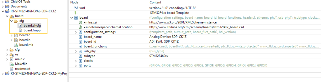
The easiest way to create custom board files is to copy the board file folder of a board similar to ours. If the folder we copied contains a subfolder named cfg, then it means that a configurator is available for the MCU in use and we may use it to automatically generate new board files. If the configurator is not available one has to manually edit the board files.
Sticking to the SDP-K1, this board comes with an STM32F469. ChibiOS provides a configurator for this MCU family, and the board folder we copied includes a cfg subfolder with an XML file named board.chcfg.
This file fully describes our board, and we can use the Eclipse XML editor to select configurations for various fields that will be used when generating the board files. These configuration files are MCU-dependent and, typically, the important things to set are
- the MCU equipped on the board
- the clock speed and voltage of the MCU
- the configuration of each pin of each port under the ports field.
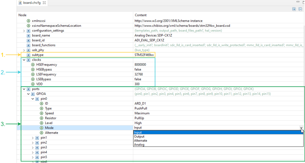
Note that many of these fields are drop-down menus such as the pinX Mode field that depends on the underlying HW and hence on the template in use.
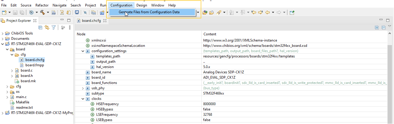
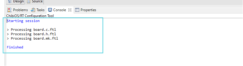
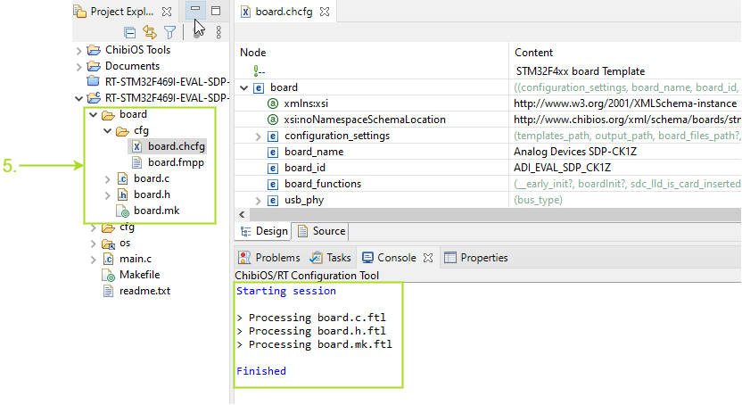
Once the XML is fine-tuned we can generate our board files: when the file board.chcfg is highlighted in the project explorer, ChibiStudio will show a new dropdown menu named Configuration. We just need to open it and choose to Generate Files from Configuration data. If the procedure is successful we will see an output in the Console window.
Adding custom board files to our project
As said before, the board files are part of the ChibiOS folder and any change to them may be lost if we update ChibiStudio or simply share the project with someone that uses an official release of ChibiOS. If we are set to create our own custom board files we may want to add them directly to our project. So a course of action would be to generate a set of board files directly in our project and then amend the makefile to point to ours instead of those from ChibiOS. To do so I followed the following steps
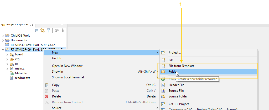
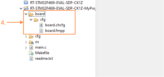
- Right-click on the project, choose New->Folder
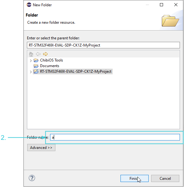
- In the newly open windows choose a name and press finish. Note that you cannot use “board” as it is already in use so in my case I placed a dummy name for now
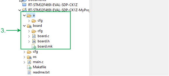
- Copy the
cfgfolder fromboardto your newly created folder (copy and paste would do fine) - Remove the board link and eventually rename your folder
- Edit your
board.chcfgand generate your board files as explained in the previous paragraph
At this point, we need to adjust a few references in the makefiles. Let us start with the newly generated board.mk file. As I did not change the board_id field, mine looks like this:
 # List of all the board related files.
BOARDSRC = $(CHIBIOS)/os/hal/boards/ADI_EVAL_SDP_CK1Z/board.c

# Required include directories
BOARDINC = $(CHIBIOS)/os/hal/boards/ADI_EVAL_SDP_CK1Z

# Shared variables
ALLCSRC += $(BOARDSRC)
ALLINC  += $(BOARDINC)
But the paths in the makefile are completely wrong as they still reference the ChibiOS folder. In my case, my project structure looks like this:
--RT-STM32F469I-EVAL-SDP-CK1Z-MyProject   - Project root
  +--board/                               - Board folder
  |  +--cfg/                              - Board configurators
  |  |  +--board.chcfg                    - Board descriptors
  |  |  +--board.fmpp                     - Board freemarkes script
  |  |  +--board.c                        - Board source file
  |  |  +--board.h                        - Board header file
  |  |  +--board.mk                       - The file we are editing
  +--cfg/                                 - Project configurations
  |  +--chconf.h                          - RT configuration file
  |  +--halconf.h                         - HAL configuration file
  |  +--mcuconf.h                         - STM32F4xx configuration file
  +--os/                                  - Link to the ChibiOS/os folder
  +--main.c                               - main.c
  +--Makefile                             - makefile
  +--readme.txt                           - readme
The goal is to update the board.mk file to accurately reflect the path of board.c relative to the makefile, as well as the relative path of the board folder. To achieve this, the following changes will be made to the board.mk file.
# List of all the board related files.
BOARDSRC = ./board/board.c

# Required include directories
BOARDINC = ./board

# Shared variables
ALLCSRC += $(BOARDSRC)
ALLINC  += $(BOARDINC)
Finally, we want to open the makefile of our project and point to this file. We hence want to change this line
include $(CHIBIOS)/os/hal/boards/ADI_EVAL_SDP_CK1Z/board.mk
into
include ./board/board.mk
so, after the changes, our sources and path section will look like this:
##############################################################################
# Project, target, sources and paths
#

# Define project name here
PROJECT = ch

# Target settings.
MCU  = cortex-m4

# Imported source files and paths.
CHIBIOS  := ../../chibios2111
CONFDIR  := ./cfg
BUILDDIR := ./build
DEPDIR   := ./.dep

# Licensing files.
include $(CHIBIOS)/os/license/license.mk
# Startup files.
include $(CHIBIOS)/os/common/startup/ARMCMx/compilers/GCC/mk/startup_stm32f4xx.mk
# HAL-OSAL files (optional).
include $(CHIBIOS)/os/hal/hal.mk
include $(CHIBIOS)/os/hal/ports/STM32/STM32F4xx/platform.mk
include ./board/board.mk
include $(CHIBIOS)/os/hal/osal/rt-nil/osal.mk
# RTOS files (optional).
include $(CHIBIOS)/os/rt/rt.mk
include $(CHIBIOS)/os/common/ports/ARMv7-M/compilers/GCC/mk/port.mk
# Auto-build files in ./source recursively.
include $(CHIBIOS)/tools/mk/autobuild.mk
# Other files (optional).
include $(CHIBIOS)/os/test/test.mk
include $(CHIBIOS)/test/rt/rt_test.mk
include $(CHIBIOS)/test/oslib/oslib_test.mk

# Define linker script file here
LDSCRIPT= $(STARTUPLD)/STM32F469xI.ld
Now that we have made changes to the makefile, we can build our project and continue working on it. It’s important to note that if we make additional changes to the board configurator and regenerate the board files, we will need to update the board.mk file again. This is because the configurator will overwrite our changes to the board.mk, so we need to make sure they reflect the correct paths for our project.
Conclusions
In conclusion, creating custom board files is an essential part of using the ChibiOS/HAL. It allows you to define the hardware-specific details of your custom development board, such as the pin configurations, clock speeds, and other settings. By following the steps outlined in this article, you can create custom board files for your specific microcontroller and board configuration. These files can be generated using the built-in configurator or manually edited, and then linked to your project via the makefiles. Custom board files ensure that your code is optimized for your hardware, and ultimately lead to a more efficient GPIO initialization during the startup phase.
Be the first to reply at How to leverage Board Files in ChibiOS