
IR Remote and STM32 using ChibiOS
IR remote
Using Infra-Red for remote control is a technology born in the 70’s and after 40 years it is still used because the good ratio performances-costs and low power consumption. IR remote require a line of sight, because of that latest remote includes bluetooth technology.
Today it is possible to buy a small remote and receiving circuitry spending a few dollars. In Embedded system using IR could be a fast and cheap solution for remote control even if nowadays RF, Bluetooth and WiFi modules are very affordable.
Lack of documentation
Searching documentation for cheap devices is often not easy at all. We cannot provide a reference manual nor datasheet for IR remote we are going to use (and even if we could most likely reader is trying to use a different device). So we want to collect here every information gathered on the internet trying to put them together pursuing our purpose: using an IR Remote.
Communication occurs through Infra Red pulses. Information is encapsulated in pulse widths: this technique is also know as PWM. We often talked about PWM on this website even if we almost used it as voltage regulation technique. Indeed we already used it ad digital communication modulation method getting data from DHT11.
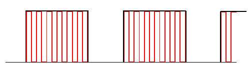
The PWM is then moved from baseband to an higher frequency depending on device. This procedure goes under the names of modulation and results in beneficial effects like noise rejection, reduction of losses during signal propagation, ability of propagate multiple signal on the same channel (air in this case). The result of this new modulation is a non-baseband PWM (See Fig.1)
Typically, carrier frequency (i.e. frequency in which is centred PWM signal after modulation) are in range of 36kHz~40kHz. If we use an IR diode (and related gain amplifier) as receiver reading signal with an oscilloscope we will see a signal similar to red signal of Fig.1. We can find some very cheap IR receiver that embeds the IR diode, a gain amplifier, a tuned filter and a Schmitt trigger. Since this receiver has a tuned filter we can find different devices for different carriers (36kHz, 36.5kHz, 37kHz, etc.).
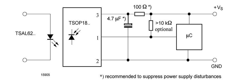
Most IR remote kit provides an IR receiver with a small PCB in which few needed passives are housed. These passives typically are a pull-up resistor and an electrolytic capacitor to filter noise on power supply, they are required specially if cables are long (see Fig.2). For the remote of this article frequency carrier is 38 kHz. Note that a IR receiver typically has three pins:
- VCC, connection to power supply (typically 2.5~5.5V, but since output depends on it we suggest 3.0V);
- GND, connection to ground;
- OUT, baseband PWM signal.
Signal on the output terminal is the envelop of IR signal i.e the baseband PWM signal (Referring to Fig.1 it is similar to the black one).
Reverse engineering
As said, information is encapsulated in square wave width. Now we need to decode signals. Proposed method is reverse engineering: we can mount circuity and write some minimal code printing on a terminal captured widths. As for DHT11 we can use ICU driver for this task, main will be something like this:
/*
    PLAY Embedded demos - Copyright (C) 2014-2015 Rocco Marco Guglielmi
    This file is part of PLAY Embedded demos.
    Licensed under the Apache License, Version 2.0 (the "License");
    you may not use this file except in compliance with the License.
    You may obtain a copy of the License at
http://www.apache.org/licenses/LICENSE-2.0
    Unless required by applicable law or agreed to in writing, software
    distributed under the License is distributed on an "AS IS" BASIS,
    WITHOUT WARRANTIES OR CONDITIONS OF ANY KIND, either express or implied.
    See the License for the specific language governing permissions and
    limitations under the License.
*/
#include "ch.h"
#include "hal.h"
#include "chprintf.h"
#define DIM  64
static BaseSequentialStream* chp = (BaseSequentialStream*) &SD2;
static void icuwidthcb(ICUDriver *icup) {
  chprintf(chp, "%d ", icuGetWidthX(icup));
}
static ICUConfig icucfg = {
  ICU_INPUT_ACTIVE_HIGH,
  10000,                                    /* 10kHz ICU clock frequency.   */
  icuwidthcb,
  NULL,
  NULL,
  ICU_CHANNEL_1,
  0
};
/*
 * Application entry point.
 */
int main(void) {
  /*
   * System initializations.
   * - HAL initialization, this also initializes the configured device drivers
   *   and performs the board-specific initializations.
   * - Kernel initialization, the main() function becomes a thread and the
   *   RTOS is active.
   */
  halInit();
  chSysInit();
  /*
   * Initializes the ICU driver 3.
   * GPIOC6 is the ICU input.
   * The two pins have to be externally connected together.
   */
  sdStart(&SD2, NULL);
  icuStart(&ICUD3, &icucfg);
  palSetPadMode(GPIOC, 6, PAL_MODE_ALTERNATE(2));
  icuStartCapture(&ICUD3);
  icuEnableNotifications(&ICUD3);
  chThdSleepMilliseconds(2000);
  /*
   * Normal main() thread activity, in this demo it does nothing.
   */
  while (true) {
    chThdSleepMilliseconds(500);
  }
  return 0;
}
Using that code we can understand certain mechanism behind the communication. As example here a copy of some test made with my IR remote
45 6 6 6 6 6 6 6 6 17 17 17 17 17 17 17 17 17 6 17 6 6 6 17 6 6 17 6 17 17 17 6 17 394 23 10769 45 6 6 6 6 6 6 6 6 18 17 18 17 17 18 17 17 6 17 17 6 6 6 17 6 17 6 6 17 18 17 6 18 394 23 8680 46 6 6 6 6 6 6 6 6 17 17 17 17 17 18 18 17 17 18 17 6 6 6 17 6 6 6 6 17 17 18 6 17 394 23 10293 46 6 6 6 6 6 6 6 6 17 18 18 18 18 17 18 17 6 6 18 6 6 6 17 6 18 17 6 18 17 17 6 18 395 23 7651 46 6 6 6 6 6 6 6 6 18 17 18 18 18 17 17 18 6 6 6 6 6 6 18 6 18 18 17 17 17 18 6 18 395 23 6385 46 6 6 6 6 6 6 6 6 17 17 17 17 17 17 18 18 17 18 6 6 6 6 18 6 6 6 18 18 17 18 6 17 394 23 11205 46 6 6 6 6 6 6 6 6 17 18 18 18 17 17 17 17 18 17 18 6 6 6 6 6 6 6 6 18 18 18 18 18 394 23 6615 46 6 6 6 6 6 6 6 6 18 18 18 18 18 17 17 17 17 6 18 6 17 6 6 6 6 18 6 18 6 18 18 17 394 23 959 23 959 23 959 23 960 23 959 23 959 23 960 23 959 23 960 23 960 23 960 23 960 23 960 23
Note that we can recognise certain repetitions. Here I pushed 8 buttons keeping pressed the last one. We can easily recognise that:
- every command is identified by a start pulse (45/46 counts i.e. 4,5 ms since ICU clock frequency is 10kHz) and an end pulse (39.4/39.5 ms);
- commands are composed by 32 bit where shortest (0.6 ms) is ‘0’ and longest (1.7/1.8 ms) is 1;
- communications are divided by a comma pulse (2.3 ms);
- commands are dead pulses between two communication (10769, 8680, 10293 counts, etc.);
- when button is kept pressed we receive a pulse (95.9/96 ms) followed by a comma that simply means repeat last command.
So we can ignore dead pulses, use start and stop to identify a command and properly recognise repeat command. Last step before write a demo is decode every button.
BTN_CH- 		0x00FFA25D
BTN_CH 			0x00FF629D
BTN_CH+ 		0x00FFE21D
BTN_PREV 		0x00FF22DD
BTN_NEXT 		0x00FF02FD
BTN_PLAY/PAUSE 	0x00FFC23D
BTN_VOL- 		0x00FFE01F
BTN_VOL+ 		0x00FFA857
BTN_EQ 			0x00FF906F
BTN_0 			0x00FF6897
BTN_100+ 		0x00FF9867
BTN_200+ 		0x00FFB04F
BTN_1 			0x00FF30CF
BTN_2 			0x00FF18E7
BTN_3 			0x00FF7A85
BTN_4			0x00FF10EF
BTN_5 			0x00FF38C7
BTN_6 			0x00FF5AA5
BTN_7 			0x00FF42BD
BTN_8 			0x00FF4AB5
BTN_9			0x00FF52AD
Proposed demo
Demo explained
The core of our demo is the ICU width callback. In this callback we have to compose the command value or detect the repeat flag. To understand following code let’s list some certitudes:
- both command and flag are completed on comma pulse;
- when we detect a start pulse, we must be ready to compose command value in the next 32 pulses;
- when we detect an end pulse the command should be composed;
- long dead pulse are useless to our purpose;
static void icuwidthcb(ICUDriver *icup) {
  icucnt_t cnt = icuGetWidthX(icup);
  if((cnt > (START_PULSE - DELTA)) && (cnt < (START_PULSE + DELTA))){
    index = 0;
    START_OCCURED = TRUE;
  }
  else if((cnt > (ONE_PULSE - DELTA)) && (cnt < (ONE_PULSE + DELTA))){
    tmp |= 1 << (31 - index);
    index++;
  }
  else if((cnt > (ZERO_PULSE - DELTA)) && (cnt < (ZERO_PULSE + DELTA))){
    tmp &= ~(1 << (31 - index));
    index++;
  }
  else if((cnt > (END_PULSE - DELTA)) && (cnt < (END_PULSE + DELTA))){
    if((START_OCCURED) && (index == 32))
      command = tmp;
    else{
      command = 0;
    }
    REPEAT_FLAG = FALSE;
    START_OCCURED = FALSE;
    index = -1;
  }
  else if((cnt > (RPT_CMD_PULSE - DELTA)) && (cnt < (RPT_CMD_PULSE + DELTA))){
    REPEAT_FLAG = TRUE;
  }
  else if((cnt > (COMMA_PULSE - DELTA)) && (cnt < (COMMA_PULSE + DELTA))){
    chEvtBroadcastFlags(&IR_receiver, 0);
  }
  else{
    /* Long dead pulse nothing to do */
  }
}
The callback above decodes IR signal and broadcast a flag on comma. Note that there are some simple check mechanism to detect uncompleted or wrong communication: as example command value is composed on a temporary variable and is copied on command only on end pulse if start pulse as been detected and 32 pulses occurred.
Concluding main() wait for events printing last command on a base sequential stream:
/*
 * Application entry point.
 */
int main(void) {
  /*
 * System initializations.
 * - HAL initialization, this also initializes the configured device drivers
 * and performs the board-specific initializations.
 * - Kernel initialization, the main() function becomes a thread and the
 * RTOS is active.
 */
  halInit();
  chSysInit();
  chEvtObjectInit(&IR_receiver);
  chEvtRegister(&IR_receiver, &el, 0);
/*
 * Initializes the ICU driver 3.
 * GPIOC6 is the ICU input.
 * The two pins have to be externally connected together.
 */
  sdStart(&SD2, NULL);
  icuStart(&ICUD3, &icucfg);
  palSetPadMode(GPIOC, 6, PAL_MODE_ALTERNATE(2));
  icuStartCapture(&ICUD3);
  icuEnableNotifications(&ICUD3);
  chThdSleepMilliseconds(2000);

  /*
 * Normal main() thread activity, in this demo it does nothing.
 */
  while (true) {
    chEvtWaitAny(ALL_EVENTS);
    switch(command){
    case BTN_CH_DOWN:
      chprintf(chp, "CH-");
      if(REPEAT_FLAG)
        chprintf(chp, " RPT");
      break;
    case BTN_CH:
      chprintf(chp, "CH");
      if(REPEAT_FLAG)
        chprintf(chp, " RPT");
      break;
    case BTN_CH_UP:
      chprintf(chp, "CH+");
      if(REPEAT_FLAG)
        chprintf(chp, " RPT");
      break;
    case BTN_PREV:
      chprintf(chp, "PREV");
      if(REPEAT_FLAG)
        chprintf(chp, " RPT");
      break;
    case BTN_NEXT:
      chprintf(chp, "NEXT");
      if(REPEAT_FLAG)
        chprintf(chp, " RPT");
      break;
    case BTN_PLAY_PAUSE:
      chprintf(chp, "PLAY/PAUSE");
      if(REPEAT_FLAG)
        chprintf(chp, " RPT");
      break;
    case BTN_VOL_DOWN:
      chprintf(chp, "VOL-");
      if(REPEAT_FLAG)
        chprintf(chp, " RPT");
      break;
    case BTN_VOL_UP:
      chprintf(chp, "VOL+");
      if(REPEAT_FLAG)
        chprintf(chp, " RPT");
      break;
    case BTN_EQ:
      chprintf(chp, "EQ");
      if(REPEAT_FLAG)
        chprintf(chp, " RPT");
      break;
    case BTN_0:
      chprintf(chp, "0");
      if(REPEAT_FLAG)
        chprintf(chp, " RPT");
      break;
    case BTN_100:
      chprintf(chp, "100+");
      if(REPEAT_FLAG)
        chprintf(chp, " RPT");
      break;
    case BTN_200:
      chprintf(chp, "200+");
      if(REPEAT_FLAG)
        chprintf(chp, " RPT");
      break;
    case BTN_1:
      chprintf(chp, "1");
      if(REPEAT_FLAG)
        chprintf(chp, " RPT");
      break;
    case BTN_2:
      chprintf(chp, "2");
      if(REPEAT_FLAG)
        chprintf(chp, " RPT");
      break;
    case BTN_3:
      chprintf(chp, "3");
      if(REPEAT_FLAG)
        chprintf(chp, " RPT");
      break;
    case BTN_4:
      chprintf(chp, "4");
      if(REPEAT_FLAG)
        chprintf(chp, " RPT");
      break;
    case BTN_5:
      chprintf(chp, "5");
      if(REPEAT_FLAG)
        chprintf(chp, " RPT");
      break;
    case BTN_6:
      chprintf(chp, "6");
      if(REPEAT_FLAG)
        chprintf(chp, " RPT");
      break;
    case BTN_7:
      chprintf(chp, "7");
      if(REPEAT_FLAG)
        chprintf(chp, " RPT");
      break;
    case BTN_8:
      chprintf(chp, "8");
      if(REPEAT_FLAG)
        chprintf(chp, " RPT");
      break;
    case BTN_9:
      chprintf(chp, "9");
      if(REPEAT_FLAG)
        chprintf(chp, " RPT");
      break;
    default:
      chprintf(chp, "Unknown");
      break;
    }
    chprintf(chp,"\n\r");
  }
  return 0;
}
Project download
The attached demo has been tested under ChibiOS 20.3.x.
RT-STM32F401RE-NUCLEO64-IR_remote_reverse-216
RT-STM32F401RE-NUCLEO64-IR_remote_21_button-216
Hi
Many thanks for this useful example. I managed to port it to STM32F769i with very little effort; however, I was forced to make few changes:
– since method icuwidthcb() is called from an ISR, I had to use chEvtBroadcastFlagsI(), else ChibiOS will throw a chSysHalt() exception & stops
– I had to change the your parameter values especially END_PULSE & START_PULSE. My remote seems to be little different (I suspect older).
– I did minor refactoring to make code in a a reusable library
– I refactored the switch statement into WEAK method with default implementation,
Click here for details
https://github.com/abusous2000/Struts4Embedded/blob/master/source/Controls/IRReceiver/
BTW, I successfully used it to control an MP3 Player, and integrated well into Struts4Embedded MVC framework. Here are more details about the framework:
http://www.chibios.com/forum/viewtopic.php?f=8&t=5601&sid=a4911bf0e861241072b72f710f3e99ac
Also I managed to I replicate similar functionality but with EBYTE Lora S32 module and FlySky i6s Remote Control (RC) too.here are the details
PPM Frame Decoder
https://github.com/abusous2000/Struts4Embedded/tree/master/source/Controls/PPMFrameDecoder
EBYTE Lora Module
https://github.com/abusous2000/Struts4Embedded/tree/master/source/Controls/eByteLora
Again, many thanks & keep up the good work.
Cheers
Thanks for reporting and for sharing I will fix my examples later on.
Note that I have a bug tracker for these projects here:
https://sourceforge.net/p/play-embedded/ticket/