
Mastering GPIOs with ChibiOS PAL: a practical guide
Introduction
The General Purpose Input/Output (GPIO) is a crucial peripheral in microcontrollers, enabling communication with the external world by sending and receiving signals through its input/output lines. GPIOs are highly configurable and versatile, with a single microcontroller often capable of hosting anywhere from a few dozen to hundreds of GPIOs. In ChibiOS\HAL, the Port Abstraction Layer (PAL) provides a dedicated API for handling GPIOs, abstracting away the hardware details of the GPIO peripheral. This allows developers to write code that is portable across different microcontrollers and platforms, while still having access to the full capabilities of the GPIOs.
Identifying GPIOs
Ports and Pads
GPIOs are organized in banks, requiring the use of both a bank identifier (often referred to as Port) and a pin number (often referred to as Pad) to identify a pin. For example, STM32 uses letters for ports (GPIOA, GPIOB, GPIOC, etc.) and numbers for pads (0 to 15), while Maxim 32 uses numbers for ports and numbers for pads but with wider banks (0 to 32).
In PAL, all APIs that address a single pad require two mandatory parameters, Port and Pad, to identify the GPIO being acted upon. PAL identifies the ports as IOPORT1, IOPORT2, IOPORT3, and so on. However, these identifiers simply redefine the platform-dependant identifier. For example, on STM32, GPIOA is identified by IOPORT1, GPIOB by IOPORT2, GPIOC by IOPORT3, and so on.
While one could use IOPORTx or GPIOx interchangeably, it is common for STM32 demos to use GPIOA, GPIOB, GPIOC, and so on as port identifiers since it makes it easier to relate the code to the schematic where a GPIO is identified by the combination of port and pad (e.g. PB3 being the label for pad 3 of GPIOB).
The code below is an excerpt of the PAL Low-Level Driver (LLD) for STM32. In this code, the abstract port identifiers (IOPORTx) are defined as aliases of the STM32-specific port identifiers (GPIOx).
/**
 * @brief   GPIO port A identifier.
 */
#if STM32_HAS_GPIOA || defined(__DOXYGEN__)
#define IOPORT1         GPIOA
#endif

/**
 * @brief   GPIO port B identifier.
 */
#if STM32_HAS_GPIOB || defined(__DOXYGEN__)
#define IOPORT2         GPIOB
#endif

/**
 * @brief   GPIO port C identifier.
 */
#if STM32_HAS_GPIOC || defined(__DOXYGEN__)
#define IOPORT3         GPIOC
#endif

/**
 * @brief   GPIO port D identifier.
 */
#if STM32_HAS_GPIOD || defined(__DOXYGEN__)
#define IOPORT4         GPIOD
#endif

/**
 * @brief   GPIO port E identifier.
 */
#if STM32_HAS_GPIOE || defined(__DOXYGEN__)
#define IOPORT5         GPIOE
#endif

/**
 * @brief   GPIO port F identifier.
 */
#if STM32_HAS_GPIOF || defined(__DOXYGEN__)
#define IOPORT6         GPIOF
#endif

/**
 * @brief   GPIO port G identifier.
 */
#if STM32_HAS_GPIOG || defined(__DOXYGEN__)
#define IOPORT7         GPIOG
#endif

/**
 * @brief   GPIO port H identifier.
 */
#if STM32_HAS_GPIOH || defined(__DOXYGEN__)
#define IOPORT8         GPIOH
#endif

/**
 * @brief   GPIO port I identifier.
 */
#if STM32_HAS_GPIOI || defined(__DOXYGEN__)
#define IOPORT9         GPIOI
#endif

/**
 * @brief   GPIO port J identifier.
 */
#if STM32_HAS_GPIOJ || defined(__DOXYGEN__)
#define IOPORT10        GPIOJ
#endif

/**
 * @brief   GPIO port K identifier.
 */
#if STM32_HAS_GPIOK || defined(__DOXYGEN__)
#define IOPORT11        GPIOK
#endif
When it comes to GPIO Pads, these are identified using simply a number. For example, on STM32 the number will go from 0 to 15 as these MCUs have GPIO banks in groups of 16 pads. To provide a simple example of the usage of Port and Pad let us consider the following API that acts on the line PK5. We will see later that this API sets the line to Logical High but to have an actual effect on PK5, this GPIO needs to be configured as a digital output.
palSetPad(GPIOK, 5U);
In ChibiOS, board files offer user-friendly aliases for each Pad, improving code readability and usability (we tackled this topic in the How to leverage board files in ChibiOS). For example, PK5 is connected to the green LED of the SDP-K1. To make the call more user-friendly, we can leverage the board files definitions and use the symbolic alias for PK5 named GPIOK_LED_GREEN shown below.
#define GPIOK_LED_GREEN 5U
In this case, our previous statement can be rephrased as follows
palSetPad(GPIOK, GPIOK_LED_GREEN);
The concept of Line
In some architectures, ChibiOS offers a single identifier called a Line that can convey both the Port and Pad values. The board files offer a list of Line identifiers for all pins that have a custom alias defined in the section named IO Lines assignments.
For example, in the board files of the SDP-K1, the Line related to PK5 is defined as follows
#define LINE_LED_GREEN PAL_LINE(GPIOK, 5U)
Leveraging this definition and the PAL API is it possible to rewrite the example of the previous paragraph in an even more compact way as
palSetLine(LINE_LED_GREEN);
Following the example just provided we may use this in our main to define custom lines. For example, let us consider that we have a common cathode RGB LED connected to our microcontroller as follows
| SDP-K1 Arduino connector | Related STM32 GPIO | RGB-LED |
|---|---|---|
| Arduino D5 | PA11 | Red Anode |
| Arduino D6 | PA10 | Green Anode |
| Arduino D7 | PG10 | Blue Anode |
| Arduino GND | – | Common Cathode |
Adopting the following definitions
#define LINE_RGB_RED                PAL_LINE(GPIOA, 11U)
#define LINE_RGB_GREEN              PAL_LINE(GPIOA, 10U)
#define LINE_RGB_BLUE               PAL_LINE(GPIOG, 10U)
We can make our code highly user-friendly and have code such as
while(true) {
  /* Setting the LED as red. */
  palSetLine(LINE_RGB_RED);
  palClearLine(LINE_RGB_GREEN);
  palClearLine(LINE_RGB_BLUE);

  chThdSleepMilliseconds(500);

  /* Setting the LED as green. */
  palClearLine(LINE_RGB_RED);
  palSetLine(LINE_RGB_GREEN);
  palClearLine(LINE_RGB_BLUE);

  chThdSleepMilliseconds(500);

  /* Setting the LED as blue. */
  palClearLine(LINE_RGB_RED);
  palClearLine(LINE_RGB_GREEN);
  palSetLine(LINE_RGB_BLUE);

  chThdSleepMilliseconds(500);
}
This hypothetical thread loop switches the color of the LED between red, green and blue with a cadency of 500ms.
Logic levels in PAL
In digital electronics, information is represented and processed using binary voltage levels: everything hence boils down to the voltage being or not being present. To accomplish that, two voltage levels are used to distinguish between the two binary states, typically represented as 0 and 1, or Logical Low and Logical High. The article Fundamentals of Digital Circuitry provides more detail and some examples of the concept of Logic Levels.
The PAL driver offers two identifiers for these two logical states and they are
/**
 * @name    Logic level constants
 * @{
 */
/**
 * @brief   Logical low state.
 */
#define PAL_LOW                         0U

/**
 * @brief   Logical high state.
 */
#define PAL_HIGH                        1U
/** @} */
These two definitions will be used later when dealing with GPIO configured as digital outputs or digital inputs.
Configuring GPIOs: the modes
Modern microcontrollers offer a variety of operational modes for each GPIO, and the PAL driver can configure all of them. However, it’s important to note that these modes are often dependent on the microcontroller architecture and may behave differently or not be supported on different models. To navigate this uncertainty, it’s necessary to refer to the documentation of the specific MCU in use.
Standard I/O modes and related APIs
In the PAL header file, you can find a set of standard modes that are expected to be implemented on every microcontroller. These Standard I/O Modes are listed below.
/**
 * @name    Pads mode constants
 * @{
 */
/**
 * @brief   After reset state.
 * @details The state itself is not specified and is architecture dependent,
 *          it is guaranteed to be equal to the after-reset state. It is
 *          usually an input state.
 */
#define PAL_MODE_RESET                  0U

/**
 * @brief   Safe state for <b>unconnected</b> pads.
 * @details The state itself is not specified and is architecture dependent,
 *          it may be mapped on @p PAL_MODE_INPUT_PULLUP,
 *          @p PAL_MODE_INPUT_PULLDOWN or @p PAL_MODE_OUTPUT_PUSHPULL for
 *          example.
 */
#define PAL_MODE_UNCONNECTED            1U

/**
 * @brief   Regular input high-Z pad.
 */
#define PAL_MODE_INPUT                  2U

/**
 * @brief   Input pad with weak pull up resistor.
 */
#define PAL_MODE_INPUT_PULLUP           3U

/**
 * @brief   Input pad with weak pull down resistor.
 */
#define PAL_MODE_INPUT_PULLDOWN         4U

/**
 * @brief   Analog input mode.
 */
#define PAL_MODE_INPUT_ANALOG           5U

/**
 * @brief   Push-pull output pad.
 */
#define PAL_MODE_OUTPUT_PUSHPULL        6U

/**
 * @brief   Open-drain output pad.
 */
#define PAL_MODE_OUTPUT_OPENDRAIN       7U
/** @} */
Note that the mode PAL_MODE_RESET and PAL_MODE_UNCONNECTED represent the default configuration and the high-Z configuration of a GPIO. These modes are highly dependent on the platform and are rarely used in practice. All the other modes will be discussed in detail later.
Configuring the mode of a GPIO at runtime
In general, all the modes can be used to configure a GPIO at runtime. To do so PAL offers an API shown below.
/**
 * @brief   Pad mode setup.
 * @details This function programs a pad with the specified mode.
 * @note    The operation is not guaranteed to be atomic on all the
 *          architectures, for atomicity and/or portability reasons you may
 *          need to enclose port I/O operations between @p osalSysLock() and
 *          @p osalSysUnlock().
 * @note    Programming an unknown or unsupported mode is silently ignored.
 * @note    The function can be called from any context.
 *
 * @param[in] port      port identifier
 * @param[in] pad       pad number within the port
 * @param[in] mode      pad mode
 *
 * @special
 */
#define palSetPadMode(port, pad, mode) pal_lld_setpadmode(port, pad, mode)
Three parameters are passed to this API: the Port, the Pad, and the Mode. As previously discussed, the Port and Pad identify the specific GPIO pin being configured. The mode instead is one of those listed before. So if as an example we would like to configure PK5 as Output Pushpull, we may want to write
palSetPadMode(GPIOK, 5, PAL_MODE_OUTPUT_PUSHPULL);
PAL offers also an API that uses the Line identifier as an alternative to the Port and Pad parameters. The following code box shows the equivalent API that uses the Line identifier.
/**
 * @brief   Line mode setup.
 * @note    The operation is not guaranteed to be atomic on all the
 *          architectures, for atomicity and/or portability reasons you may
 *          need to enclose port I/O operations between @p osalSysLock() and
 *          @p osalSysUnlock().
 * @note    The function can be called from any context.
 *
 * @param[in] line      line identifier
 * @param[in] mode      pad mode
 *
 * @special
 */
#define palSetLineMode(line, mode) pal_lld_setlinemode(line, mode)
Rewriting the previous example about PK5 using this API and leveraging once again the board definition we would have once more a user-friendly line that clearly states that the line connected to the green LED is configured as output Push-pull.
palSetLineMode(LINE_LED_GREEN, PAL_MODE_OUTPUT_PUSHPULL);
To complete the picture, let us revise the RGB LED example we made a few chapters ago while speaking about line identifiers. We now know that the GPIO lines connected to the LED must first be configured as outputs to see any changes on the LED. The code snippet below extends the previous example and shows how the lines are configured as Output PushPull, which is the mode required to drive an LED
/* Definfing the lines. */
#define LINE_RGB_RED                PAL_LINE(GPIOA, 11U)
#define LINE_RGB_GREEN              PAL_LINE(GPIOA, 10U)
#define LINE_RGB_BLUE               PAL_LINE(GPIOG, 10U)

/* Configuring the lines as Output PushPull */
palSetLineMode(LINE_RGB_RED, PAL_MODE_OUTPUT_PUSHPULL);
palSetLineMode(LINE_RGB_GREEN, PAL_MODE_OUTPUT_PUSHPULL);
palSetLineMode(LINE_RGB_BLUE, PAL_MODE_OUTPUT_PUSHPULL);

while(true) {
  /* Setting the LED as red. */
  palSetLine(LINE_RGB_RED);
  palClearLine(LINE_RGB_GREEN);
  palClearLine(LINE_RGB_BLUE);

  chThdSleepMilliseconds(500);

  /* Setting the LED as green. */
  palClearLine(LINE_RGB_RED);
  palSetLine(LINE_RGB_GREEN);
  palClearLine(LINE_RGB_BLUE);

  chThdSleepMilliseconds(500);

  /* Setting the LED as blue. */
  palClearLine(LINE_RGB_RED);
  palClearLine(LINE_RGB_GREEN);
  palSetLine(LINE_RGB_BLUE);

  chThdSleepMilliseconds(500);
}
Configuring a group of GPIOs at runtime
The API palSetLineMode is actually a subset of a more generic API that allows configuring a group of pads belonging to the same GPIO. This API is called palSetGroupMode, and it allows you to configure at once a group of pins belonging to the same Port with the same mode. To use this API, you need to pass four arguments
/**
 * @brief   Pads group mode setup.
 * @details This function programs a pads group belonging to the same port
 *          with the specified mode.
 * @note    The operation is not guaranteed to be atomic on all the
 *          architectures, for atomicity and/or portability reasons you may
 *          need to enclose port I/O operations between @p osalSysLock() and
 *          @p osalSysUnlock().
 * @note    Programming an unknown or unsupported mode is silently ignored.
 * @note    The function can be called from any context.
 *
 * @param[in] port      port identifier
 * @param[in] mask      group mask
 * @param[in] offset    group bit offset within the port
 * @param[in] mode      group mode
 *
 * @special
 */
#define palSetGroupMode(port, mask, offset, mode)                           \
  pal_lld_setgroupmode(port, mask, offset, mode)
While we have already mentioned port and mode, the parameters mask and offset may be unfamiliar to those who are new to embedded programming. The mask specifies which pins of the port will be affected by the changes made using the API, while the offset indicates the position of the least significant bit of the mask. The best way to understand the concept of mask and offset is by using examples.
Let us say that we want to configure both PA4, PA5 and PA6 as Output push-pull. In a port of 16 bits, the mask to apply would be in binary
#define MY_MASK                         0b0000000001110000 /* 0x0070 */
#define MY_OFFSET                       0
where a 0 means that the pin will not be affected by the changes and 1 that the pin will be affected by the changes. Considering that the first pad we are going to change is in the 4th position counting from the right, we can rewrite this using the offset
#define MY_MASK                         0b0000000000000111 /* 0x0007 */
#define MY_OFFSET                       4
This brings us to the examples
/* The following statements are equivalent. However, the last statement
   sacrifices some compactness in exchange for clarity. */
palSetGroupMode(GPIOA, 0x0070, 0, PAL_MODE_OUTPUT_PUSHPULL);
palSetGroupMode(GPIOA, 0x0007, 4, PAL_MODE_OUTPUT_PUSHPULL);
palSetGroupMode(GPIOA, PAL_PORT_BIT(4) | PAL_PORT_BIT(5) | PAL_PORT_BIT(6),
                0, PAL_MODE_OUTPUT_PUSHPULL);
Note that in the last line, we used some macros and the OR bitwise to compose the mask previously hard coded. If you are unfamiliar with bitmasking the article Registers and bit masks can help to shed some light on the matter.
Another example would be configuring PB3 and PB15 as Input pull-up. This would look like
palSetGroupMode(GPIOB, PAL_PORT_BIT(3) | PAL_PORT_BIT(15), 0,
                PAL_MODE_INPUT_PULLUP);
Platform-specific I/O modes: the SDP-k1 case
Every microcontroller has a unique register interface to configure the behavior of its GPIOs. In the case of the SDP-K1 evaluation board, it is equipped with the STM32F4 microcontroller, which uses the STM32 GPIOv2 driver.
Side note, GPIOv2 is compatible with almost all STM32 microcontrollers, except for the STM32F1 which uses GPIOv1 and the STM32L4 which uses GPIOv3. GPIOv3 is a superset of GPIOv2 that provides additional modes for low-power applications. To learn more about how ChibiOS/HAL abstracts these differences between microcontroller families, you can read the article ChibiOS/HAL design: an object-oriented approach. Long side note short, the following cover 90% of the STM32 families.
In STM32 GPIOv2 each GPIO is configured using a combination of 5 types of flags:
- Mode chooses the primary behavior
- Output type (OTYPE) chooses the behavior of an output line
- Output speed (OSPEED) specifies the slew rate of an output line
- Pull-up/pull-down (PUPDR) determines if the GPIO has an internal pull resistor
- Alternate Function specifies the GPIO routing to internal peripherals when mode is set to Alternate
The following snippet includes all possible flags. Take a quick look at it, but don’t focus too much on it, as the relevant flags will be discussed in detail in the appropriate chapter.
/**
 * @name    STM32-specific I/O mode flags
 * @{
 */
#define PAL_STM32_MODE_MASK             (3U << 0U)
#define PAL_STM32_MODE_INPUT            (0U << 0U)
#define PAL_STM32_MODE_OUTPUT           (1U << 0U)
#define PAL_STM32_MODE_ALTERNATE        (2U << 0U)
#define PAL_STM32_MODE_ANALOG           (3U << 0U)

#define PAL_STM32_OTYPE_MASK            (1U << 2U)
#define PAL_STM32_OTYPE_PUSHPULL        (0U << 2U)
#define PAL_STM32_OTYPE_OPENDRAIN       (1U << 2U)

#define PAL_STM32_OSPEED_MASK           (3U << 3U)
#define PAL_STM32_OSPEED_LOWEST         (0U << 3U)
#if defined(STM32F0XX) || defined(STM32F30X) || defined(STM32F37X)
#define PAL_STM32_OSPEED_MID            (1U << 3U)
#else
#define PAL_STM32_OSPEED_MID1           (1U << 3U)
#define PAL_STM32_OSPEED_MID2           (2U << 3U)
#endif
#define PAL_STM32_OSPEED_HIGHEST        (3U << 3U)

#define PAL_STM32_PUPDR_MASK            (3U << 5U)
#define PAL_STM32_PUPDR_FLOATING        (0U << 5U)
#define PAL_STM32_PUPDR_PULLUP          (1U << 5U)
#define PAL_STM32_PUPDR_PULLDOWN        (2U << 5U)

#define PAL_STM32_ALTERNATE_MASK        (15U << 7U)
#define PAL_STM32_ALTERNATE(n)          ((n) << 7U)
These flags can be combined together using bitwise OR. The following code demonstrates how they are combined to implement the Standard I/O Modes of the PAL driver.
/**
 * @name    Standard I/O mode flags
 * @{
 */
/**
 * @brief   Implemented as input.
 */
#define PAL_MODE_RESET                  PAL_STM32_MODE_INPUT

/**
 * @brief   Implemented as input with pull-up.
 */
#define PAL_MODE_UNCONNECTED            PAL_MODE_INPUT_PULLUP

/**
 * @brief   Regular input high-Z pad.
 */
#define PAL_MODE_INPUT                  PAL_STM32_MODE_INPUT

/**
 * @brief   Input pad with weak pull up resistor.
 */
#define PAL_MODE_INPUT_PULLUP           (PAL_STM32_MODE_INPUT |             \
                                         PAL_STM32_PUPDR_PULLUP)

/**
 * @brief   Input pad with weak pull down resistor.
 */
#define PAL_MODE_INPUT_PULLDOWN         (PAL_STM32_MODE_INPUT |             \
                                         PAL_STM32_PUPDR_PULLDOWN)

/**
 * @brief   Analog input mode.
 */
#define PAL_MODE_INPUT_ANALOG           PAL_STM32_MODE_ANALOG

/**
 * @brief   Push-pull output pad.
 */
#define PAL_MODE_OUTPUT_PUSHPULL        (PAL_STM32_MODE_OUTPUT |            \
                                         PAL_STM32_OTYPE_PUSHPULL)

/**
 * @brief   Open-drain output pad.
 */
#define PAL_MODE_OUTPUT_OPENDRAIN       (PAL_STM32_MODE_OUTPUT |            \
                                         PAL_STM32_OTYPE_OPENDRAIN)
/** @} */
For example, note that the mode PAL_MODE_OUTPUT_PUSHPULL on STM32 is actually implemented by combining a MODE flag and an OTYPE flag. The following two lines are hence completely equivalent
/* Setting Line RGB RED as Output Push Pull using the STM32 flag. */
palSetLineMode(LINE_RGB_RED, PAL_STM32_MODE_OUTPUT | PAL_STM32_OTYPE_PUSHPULL);

/* Setting Line RGB RED as Output Push Pull using the PAL Standard I/O Mode flag. */
palSetLineMode(LINE_RGB_RED, PAL_MODE_OUTPUT_PUSHPULL);
Note that the second statement is more platform-agnostic by avoiding the use of flags with the PAL_STM32 prefix. In general, is a good practice to avoid platform-dependent flags to ensure code portability but unfortunately not always possible.
Finally, before moving forward, the STM32 GPIOv2 LLD adds another special mode to complete the Standard I/O Modes. This mode allows rerouting a GPIO to one of the internal peripherals. This mode, presented in the following box will also be discussed in detail in a later chapter.
/**
 * @brief   Alternate function.
 *
 * @param[in] n         alternate function selector
 */
#define PAL_MODE_ALTERNATE(n)           (PAL_STM32_MODE_ALTERNATE |         \
                                         PAL_STM32_ALTERNATE(n))
Board level initialization
While the PAL API offers a way to configure the GPIO at run time, it is important to note that the board files provide some board-specific configurations, such as the pin and line identifiers, and they initialize the entire GPIO memory bank before the user application starts. If you have a custom board or you want to customize the initial configuration of the GPIOs, you may need to create your own custom board files. The board files, as well as the process of generating customized ones, are explained in How to leverage Board Files in ChibiOS.
GPIOs as Digital Output
A GPIO configured as digital output allows you to drive the signal as either Logical High or Logical Low usually to control external devices such as LEDs, motors, or relays.
There are two fundamental types of Digital Output:
- Output Push-Pull, which can drive the signal either high or low. In this configuration, the GPIO pin is connected to a load or an external circuit that expects a voltage to be applied to it. When the GPIO output is high, the load receives a high voltage, and when the GPIO output is low, the load receives a low voltage.
- Output Open-Drain, which can only drive the signal low. In this configuration, when the GPIO output is high, the GPIO pin is in a high-impedance state, which disconnects the load from the internal circuitry of the GPIO. This configuration is often used in combination with a pull-up resistor that pulls the line high when the GPIO is in a high-impedance state.
More details about the output configurations can be found in the article Fundamentals of Digital Circuitry.
Configuring pins as digital output can simply be done using palSetPadMode, palSetLineMode or palSetGroupMode to configure a GPIO as either PAL_MODE_OUTPUT_PUSHPULL or PAL_MODE_OUTPUT_OPENDRAIN.
/* Defining some lines. */
#define LINE_LED_BLUE               PAL_LINE(GPIOA, 3U)
#define LINE_BUZZER                 PAL_LINE(GPIOA, 4U)
#define LINE_CONTENDER              PAL_LINE(GPIOA, 5U)


/* Configuring PA3 to behave as Output Push-Pull. */
palSetPadMode(GPIOA, 3, PAL_MODE_OUTPUT_PUSHPULL);

/* This line is equivalent to the previous one. */
palSetLineMode(LINE_LED_BLUE, PAL_MODE_OUTPUT_PUSHPULL);

/* Setting a line as Output Open-Drain. */
palSetLineMode(LINE_CONTENDER, PAL_MODE_OUTPUT_OPENDRAIN);

/* Setting a line as Output Open-Drain with internal pull-Up.
   This configuration is going to overwrite the previous one.
   Note that this configuration uses an STM32-specific flag. */
palSetLineMode(LINE_CONTENDER, PAL_MODE_OUTPUT_OPENDRAIN |
                               PAL_STM32_PUPDR_PULLUP);
The article Fundamentals of Digital Circuitry provides more detail and some examples of the concept of Logic Levels, as well as the Push-Pull and Open-Drain configurations.
palSet, PalClear and palToggle
When a GPIO is configured as Digital Output, there are three main operations that can be performed:
- Set it to a high logical level
- Set it to a low logical level
- Invert its state (i.e. set it low when it is high and vice versa)
These three operations are embodied in the following 3 APIs
/**
 * @brief   Sets a pad logic state to @p PAL_HIGH.
 * @note    The operation is not guaranteed to be atomic on all the
 *          architectures, for atomicity and/or portability reasons you may
 *          need to enclose port I/O operations between @p osalSysLock() and
 *          @p osalSysUnlock().
 * @note    The function can be called from any context.
 *
 * @param[in] port      port identifier
 * @param[in] pad       pad number within the port
 *
 * @special
 */
#define palSetPad(port, pad) pal_lld_setpad(port, pad)

/**
 * @brief   Clears a pad logic state to @p PAL_LOW.
 * @note    The operation is not guaranteed to be atomic on all the
 *          architectures, for atomicity and/or portability reasons you may
 *          need to enclose port I/O operations between @p osalSysLock() and
 *          @p osalSysUnlock().
 * @note    The function can be called from any context.
 *
 * @param[in] port      port identifier
 * @param[in] pad       pad number within the port
 *
 * @special
 */
#define palClearPad(port, pad) pal_lld_clearpad(port, pad)

/**
 * @brief   Toggles a pad logic state.
 * @note    The operation is not guaranteed to be atomic on all the
 *          architectures, for atomicity and/or portability reasons you may
 *          need to enclose port I/O operations between @p osalSysLock() and
 *          @p osalSysUnlock().
 * @note    The function can be called from any context.
 *
 * @param[in] port      port identifier
 * @param[in] pad       pad number within the port
 *
 * @special
 */
#define palTogglePad(port, pad) pal_lld_togglepad(port, pad)
Similarly, a Line based API set is offered
/**
 * @brief   Sets a line logic state to @p PAL_HIGH.
 * @note    The operation is not guaranteed to be atomic on all the
 *          architectures, for atomicity and/or portability reasons you may
 *          need to enclose port I/O operations between @p osalSysLock() and
 *          @p osalSysUnlock().
 * @note    The function can be called from any context.
 *
 * @param[in] line      line identifier
 *
 * @special
 */
#define palSetLine(line) palSetPad(PAL_PORT(line), PAL_PAD(line))

/**
 * @brief   Clears a line logic state to @p PAL_LOW.
 * @note    The operation is not guaranteed to be atomic on all the
 *          architectures, for atomicity and/or portability reasons you may
 *          need to enclose port I/O operations between @p osalSysLock() and
 *          @p osalSysUnlock().
 * @note    The function can be called from any context.
 *
 * @param[in] line      line identifier
 *
 * @special
 */
#define palClearLine(line) palClearPad(PAL_PORT(line), PAL_PAD(line))

/**
 * @brief   Toggles a line logic state.
 * @note    The operation is not guaranteed to be atomic on all the
 *          architectures, for atomicity and/or portability reasons you may
 *          need to enclose port I/O operations between @p osalSysLock() and
 *          @p osalSysUnlock().
 * @note    The function can be called from any context.
 *
 * @param[in] line      line identifier
 *
 * @special
 */
#define palToggleLine(line) palTogglePad(PAL_PORT(line), PAL_PAD(line))
An example of the use of the palToggleLine API can be found in The simplest project ever with ChibiOS. It’s worth noting that in this particular case, there was no need to configure the mode of LINE_LED_GREEN as the board files already took care of it. However, if you’re using an external device such as a LED, you may need to configure the mode yourself. You can refer to the board header file to find out how each pin has been configured at board-initialization time.
Additional output APIs
PAL provides an additional API that allows the logical state of a pad to be written. Additionally, all the APIs mentioned earlier can be extended to handle the entire port or a group of pins belonging to the same port. While these functions are briefly mentioned for completeness, they are rarely used in everyday applications.
palWritePad and palWriteLine
/**
 * @brief   Writes a logic state on an output pad.
 * @note    The operation is not guaranteed to be atomic on all the
 *          architectures, for atomicity and/or portability reasons you may
 *          need to enclose port I/O operations between @p osalSysLock() and
 *          @p osalSysUnlock().
 * @note    The function can be called from any context.
 *
 * @param[in] port      port identifier
 * @param[in] pad       pad number within the port
 * @param[in] bit       logic value, the value must be @p PAL_LOW or
 *                      @p PAL_HIGH
 *
 * @special
 */
#define palWritePad(port, pad, bit) pal_lld_writepad(port, pad, bit)

/**
 * @brief   Writes a logic state on an output line.
 * @note    The operation is not guaranteed to be atomic on all the
 *          architectures, for atomicity and/or portability reasons you may
 *          need to enclose port I/O operations between @p osalSysLock() and
 *          @p osalSysUnlock().
 * @note    The function can be called from any context.
 *
 * @param[in] line      line identifier
 * @param[in] bit       logic value, the value must be @p PAL_LOW or
 *                      @p PAL_HIGH
 *
 * @special
 */
#define palWriteLine(line, bit) pal_lld_writeline(line, bit)
With palWritePad and palWriteLine you can set the logical state of the port by choosing bit as PAL_HIGH or PAL_LOW. The following example should clarify any doubt.
/* The following two statements are equivalent both set the line to high. */
palSetLine(LINE_LED_GREEN);
palWriteLine(LINE_LED_GREEN, PAL_HIGH);

/* Similarly both here set the line to low. */
palClearLine(LINE_LED_GREEN);
palWriteLine(LINE_LED_GREEN, PAL_LOW);
Handling the entire port or group of pads
It should come as no surprise that it is possible to set, clear, and toggle an entire port. It is also possible to write to a port or a group by choosing the status of each pad separately. The following example demonstrates how to do so. Pay attention to the comments that explain what will happen in the next line of code.
/* Configuring all 16 pins of GPIOC (PC0 to PC15) as output push-pull. */
palSetGroupMode(GPIOC, 0xFFFF, 0, PAL_MODE_OUTPUT_PUSHPULL);

/* Setting all 16 pins of the port to logic high. */
palSetPort(GPIOC);

/* Setting all 16 pins of the port to logic low. */
palClearPort(GPIOC);

/* Setting the first half of the port (PC0 to PC7) to logic high and
the second half (PC8 to PC15) to logic low. */
palWritePort(GPIOC, 0x00FF);

/* Setting PC0 to logic high, PC1 to logic low, and PC2 to logic high,
while leaving PC3 to PC15 unchanged. */
palWriteGroup(GPIOC, PAL_BIT(0) | PAL_BIT(1) | PAL_BIT(2), 0, 0x0005);
Note that there is a difference between palWritePort and PalWriteGroup. The palWritePort function affects all pins of a port, whereas the PalWriteGroup function only affects the pins that are masked. Similar to palSetGroupMode, the PalWriteGroup API takes four parameters, and the same considerations for mask and offset that were mentioned earlier still apply.
/**
 * @brief   Writes a group of bits.
 * @note    The operation is not guaranteed to be atomic on all the
 *          architectures, for atomicity and/or portability reasons you may
 *          need to enclose port I/O operations between @p osalSysLock() and
 *          @p osalSysUnlock().
 * @note    The function can be called from any context.
 *
 * @param[in] port      port identifier
 * @param[in] mask      group mask, a logic AND is performed on the
 *                      output  data
 * @param[in] offset    group bit offset within the port
 * @param[in] bits      bits to be written. Values exceeding the group
 *                      width are masked.
 *
 * @special
 */
#define palWriteGroup(port, mask, offset, bits)                             \
  pal_lld_writegroup(port, mask, offset, bits)
GPIOs as Digital Input
A GPIO configured as a digital input allows the microcontroller to read the logical state of a line, which can be either high or low depending on the state of the external device connected to the pin. Typically, this pin is connected to a sensor or switch, and the microcontroller can read the state of the sensor or switch through the GPIO pin. In many microcontrollers, an internal Schmitt Trigger filters the input signal and consequently when the pin is configured as a digital input, it behaves as a High-Z line, which means that if the external device is disconnected, the line can be floating between PAL_HIGH and PAL_LOW. In this case, if enough noise hits the pin, the trigger may continuously switch between VDD and ground generating additional digital noise on the lines nearby.
To address this issue, an external pull-up or pull-down resistor can be used to enforce the status of the line when no voltage is applied. Some microcontrollers also have an internal pull resistor, typically in the order of hundreds of ohms. There are three possible modes for an input pin:
PAL_MODE_INPUT, digital input with no internal pull resistorPAL_MODE_INPUT_PULLUP, digital input with an internal pull-up resistorPAL_MODE_INPUT_PULLDOWN, digital input with an internal pull-down resistor.
Before continuing, we once again recommend referring to the article Fundamentals of Digital Circuitry to learn about the benefits of a Schmitt Trigger as a digital input filter, as well as how to pull resistors work and how to properly size them.
palRead
Reading a Digital Input GPIO can be easily done using the APIs palReadPad, palReadLine. This API is the counterpart of the palWritePad and palWriteLine and returns the logical state of the pad read. For example, reading a line would look like
/* Defining a lines. */
#define LINE_INPUT                  PAL_LINE(GPIOA, 3U)

/* Configuring the line as Input pull-up. */
palSetLineMode(LINE_INPUT, PAL_MODE_INPUT_PULLUP);

if(palReadLine(LINE_INPUT) == PAL_HIGH) {
  /* The line is high. */
}
else {
  /* The line is low. */
}
The concept can be extended to a group of pads or even the entire port using the APIs palReadGroup and palReadPort. In this case, the APIs return a mask that represents the value of each bit of the port. Let us assume that we are having PC0, PC1, PC2 and PC3 connected to some digital input lines and I want to read them simultaneously. The code would look like this:
/* Defining the GPIO mask. */
#define GPIOC_MASK                  PAL_PORT_BIT(0) | PAL_PORT_BIT(1) | \
                                    PAL_PORT_BIT(2) | PAL_PORT_BIT(3)

/* Configuring the lines as Input pull-up. */
palSetGroupMode(GPIOC, GPIOC_MASK, 0, PAL_MODE_INPUT_PULLUP);

/* Reading the GPIOC group status. */
uint16_t group_status = palReadGroup(GPIOC, GPIOC_MASK, 0);

if(group_status & PAL_PORT_BIT(0)) {
  /* PC0 is high. */
}
else {
  /* PC0 is low. */
}

if(group_status & PAL_PORT_BIT(1)) {
  /* PC1 is high. */
}
else {
  /* PC1 is low. */
}

if(group_status & PAL_PORT_BIT(2)) {
  /* PC2 is high. */
}
else {
  /* PC2 is low. */
}

if(group_status & PAL_PORT_BIT(3)) {
  /* PC3 is high. */
}
else {
  /* PC3 is low. */
}
Final notes about the palRead functions
On many microcontroller architectures, the APIs palReadPort and palReadLine can also be used to check the electrical state of a Digital Output. For instance, if a Digital Output pin is shorted to the ground, trying to set it to a high logical state will not produce any change in the output, and reading back the line using palReadLine can be used to detect the short circuit. However, it should be noted that palReadLatch function is more closely related to Digital Outputs than digital inputs, as it can be used to read the status of the Output latch of a port.
GPIOs as Analog Input/Output
Many microcontrollers support connecting GPIO to internal analog peripherals such as Analog to Digital (ADC) or Digital to Analog (DAC) converters. In the case of ADC, the GPIO needs to behave as an analog input, and in the case of DAC, as an analog output. In such scenarios, Schmitt Trigger, push-pull/open-drain output drivers, and pull resistors should not be on the signal path as they may damage signal integrity.
The configuration to be adopted in this case depends on the microcontroller’s architecture. For example, for STM32, the mode for both DAC and ADC is PAL_MODE_INPUT_ANALOG. Once the GPIO is configured properly, the internal ADC and DAC of the microcontroller can be used by referring to the ADC and DAC drivers of ChibiOS, which will be discussed in a later article.
An old article titled Using STM32 ADC with ChibiOS ADC Driver provides some good references. However, we plan to rewrite it in the near future.
Rerouting GPIOs to internal peripherals: the alternate functions
The alternate mode is something very STM32-specific but it is often implemented similarly on other microcontrollers even if using a different name. The STM32 is equipped with a big number of internal peripherals such as USARTs, SPIs, I2Cs and Timers which are interconnected to GPIO pins through multiplexers.
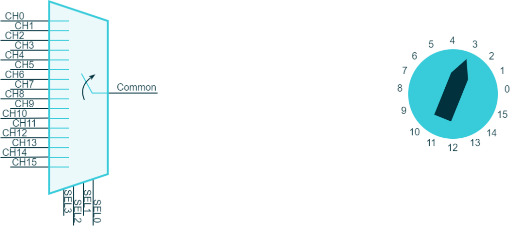
A multiplexer is an electronic circuit that allows multiple signal channels to be rerouted to a common channel. A digital multiplexer accepts a value that selects which line is routed to the common channel. Only one channel can be routed at a time. For example, let’s consider a 16-way multiplexer. In this case, the selector word will be 4 bits, not bytes. The selector value from 0 to 15 will choose which channel from 1 to 16 will be routed to the common channel.
The alternate functions of STM32 utilize a multiplexer to enable the connection between GPIO and internal peripherals. A selector is used to specify which channel is connected to the GPIO, with each channel representing the I/O of an internal peripheral. Each pad can have up to 16 possibilities, hence the PAL_MODE_ALTERNATE function receives a parameter that represents the value of the selector of the multiplexer.
/**
 * @brief   Alternate function.
 *
 * @param[in] n         alternate function selector
 */
#define PAL_MODE_ALTERNATE(n)           (PAL_STM32_MODE_ALTERNATE |         \
                                         PAL_STM32_ALTERNATE(n))
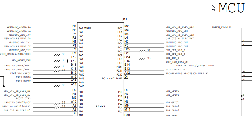
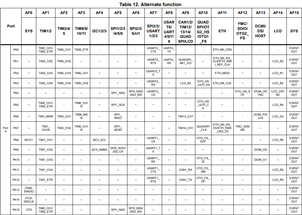
It is important to note that the mapping of internal peripheral I/O to GPIOs depends not only on the STM32 family being used but also on the specific part ID and physical connections on the chip. Therefore, this information is included in the datasheet of the microcontroller being used. For example, for the SDP-K1 we have to consider the datasheet of the STM32F469NI: in this document, there is a table that contains the configuration matrix of each GPIO. As example below the configuration matrix of the GPIOA.
For the sake of understanding let us consider the STM32F469 that is the MCU hosted on the SDP-K1 and let us take a look at the pinout map of the board.
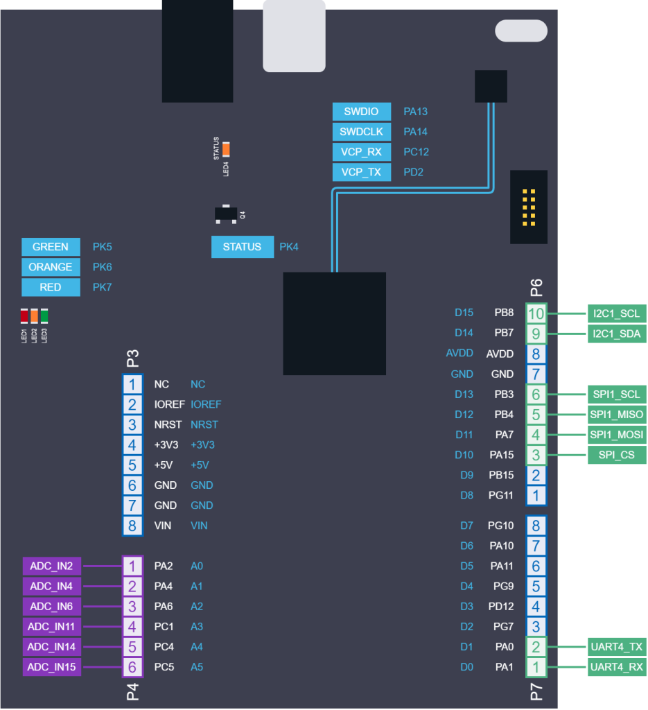
The Arduino connector specifies that on pins D10 to D13, there should be some GPIOs that are internally wired to an SPI peripheral. Our pin map helps you to identify that
| Arduino Connector label | STM32 GPIO label | Function |
|---|---|---|
| ARD_D10 | PA15 | SPI Chip Select |
| ARD_D11 | PA7 | SPI1 Master Output Slave Input |
| ARD_D12 | PB4 | SPI1 Master Input Slave Output |
| ARD_D13 | PB3 | SPI1 Clock |
Looking at the datasheet is possible to complete the previous table with the needed alternate functions
| Arduino Connector label | STM32 GPIO label | Alternate Function | Function |
|---|---|---|---|
| ARD_D10 | PA15 | AF5 | SPI Chip Select |
| ARD_D11 | PA7 | AF5 | SPI1 Master Output Slave Input |
| ARD_D12 | PB4 | AF5 | SPI1 Master Input Slave Output |
| ARD_D13 | PB3 | AF5 | SPI1 Clock |
Thus, configuring those pins to be routed to the SPI might appear as follows:
  palSetLineMode(LINE_ARD_D10, PAL_MODE_ALTERNATE(5));
  palSetLineMode(LINE_ARD_D11, PAL_MODE_ALTERNATE(5));
  palSetLineMode(LINE_ARD_D12, PAL_MODE_ALTERNATE(5));
  palSetLineMode(LINE_ARD_D13, PAL_MODE_ALTERNATE(5));
In reality, the CS line is typically controlled in software mode (i.e. it is handled as a normal digital output line), and to cope with the high speed of the SPI, it is always a good idea to set the output speed to the maximum rate. The previous code would then become something like this:
  palSetLineMode(LINE_ARD_D10, PAL_MODE_OUTPUT_PUSHPULL);
  palSetLineMode(LINE_ARD_D11, PAL_MODE_ALTERNATE(5) | PAL_STM32_OSPEED_HIGHEST);
  palSetLineMode(LINE_ARD_D12, PAL_MODE_ALTERNATE(5) | PAL_STM32_OSPEED_HIGHEST);
  palSetLineMode(LINE_ARD_D13, PAL_MODE_ALTERNATE(5) | PAL_STM32_OSPEED_HIGHEST);
Conclusions
This article has provided a comprehensive overview of GPIOs, including their modes and various APIs available in the PAL library for configuring and manipulating them. We have also explored platform-specific I/O modes using the SDP-K1 board as an example. By mastering these concepts, developers can efficiently leverage the GPIO capabilities of microcontrollers and build robust embedded systems.
It’s important to note that this article is just one piece of the puzzle. To gain a full understanding of PAL and GPIOs, we recommend checking out our companion articles on Fundamentals of Digital Circuitry and How to leverage Board Files in ChibiOS.
Additionally, our articles on Hands-on exercises with LEDs and ChibiOS PAL and Mastering push buttons with ChibiOS PAL: Hands-on exercises can be helpful references for practicing the usage of PAL. With these resources at hand, developers can take full advantage of the capabilities of microcontrollers and gain more extend their possibilities with embedded system applications.
Be the first to reply at Mastering GPIOs with ChibiOS PAL: a practical guide