
Mastering push buttons with ChibiOS PAL: Hands-on exercises
Introduction
Digital inputs are one of the primary ways embedded systems interface with the external world, allowing device-to-device communication and MCUs to respond to user inputs or environmental changes. In our previous article, we covered the fundamentals of the PAL driver of ChibiOS/HAL, which provides a powerful and versatile API for working with digital inputs. In this article, we will take a step further by going hands-on and analyzing real-world examples using push-buttons, one of the simplest and most common digital inputs.
By diving into these practical exercises, you will gain a deeper understanding of various techniques to handle buttons, such as polling and event-driven methods, and learn effective debouncing strategies. This article is designed to enhance your skills and confidence in handling digital inputs in your embedded system projects, regardless of your experience level.
Before diving into this article, we recommend reviewing the following resources to establish a solid foundation in digital circuitry and the PAL driver of ChibiOS. Here’s the full list of those articles, and we will refer to them when needed throughout this article:
- Fundamentals of Digital Circuitry, which explores the fundamental concepts of digital electronics, including logic levels, push-pull and open-drain configurations, pull-up and pull-down resistors, the first-order RC circuit and the Schmitt trigger.
- Mastering GPIOs with ChibiOS PAL: a practical guide, that gets covered the working principles of a GPIO and the related API of the PAL driver in ChibiOS/RT HAL.
- Mastering External Interrupts with ChibiOS PAL: From Polling to Events, which goes a step further in exploring the PAL API, detailing the event mechanisms to leverage external interrupts.
In this article, we will be using the Analog Devices SDP-K1 evaluation kit. Please note that you can use any other microcontroller supported by ChibiOS, as long as you remain attentive to the differences in routing connections and configuring GPIOs. This will ensure a smooth and successful project experience.
Push-buttons
A quick refresher
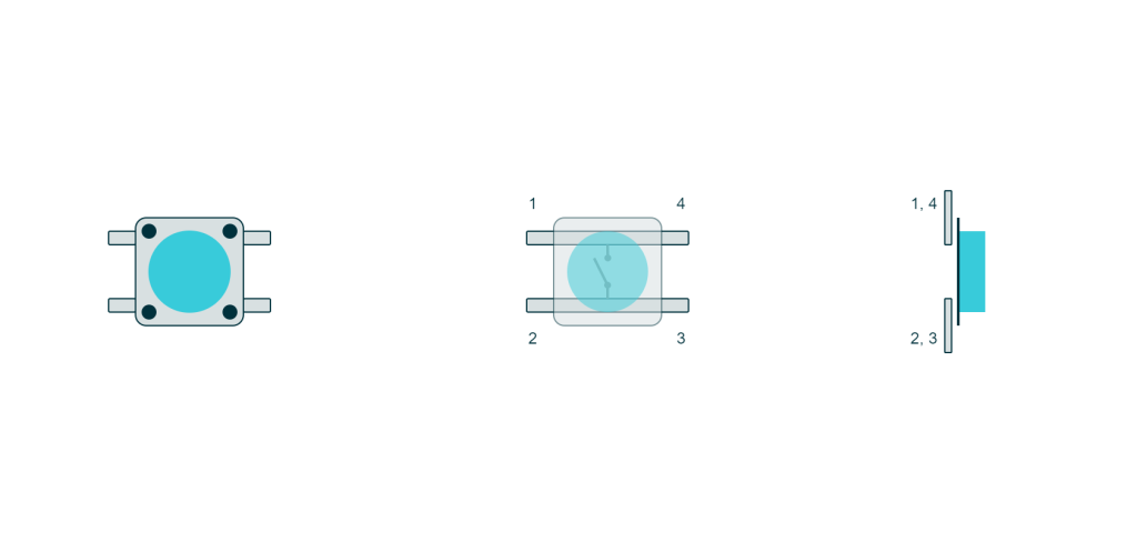
A push-button is a switch equipped with a spring that allows it to assume two states: pushed or released. Under normal conditions, the button remains in the released state due to the spring.
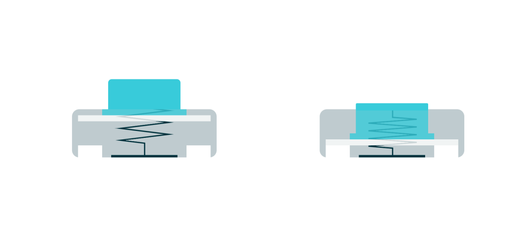
From a circuit perspective, a push-button is a two-terminal device that acts as a short circuit when pushed and an open circuit when released.
Push-buttons are inexpensive and easy to use, making them widely used in embedded systems as simple input devices. They can be connected between a digital input line and one of the two voltage rails, pulling the line high or low when pressed. However, when the button is released, the line behaves as a High-Z line, meaning that the line may float between the two supply rails. In such cases, if enough noise impacts the pin, the Schmitt trigger may continuously switch between VDD and ground, generating additional digital noise on nearby lines. To address this issue, buttons are often used with pull resistors.
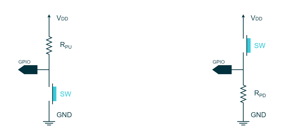
Depending on which side the button is connected to, it can be considered active low (i.e. the line goes low when the button is pressed and high when released) or active high (i.e. the line goes low when the button is pressed and high when released).
The choice of the pull-up resistor
Push-buttons can achieve an acceptable transient time even when coupled with a weak 400kΩ pull resistor. Many breakout boards are already equipped with pull resistors in the order of 10kΩ. However, if the breakout board you plan to use does not have any pull resistor, or if you want to connect a button using a breadboard, the internal pull resistor of the microcontroller is sufficient for this application. For more information on this topic, refer to the appendix at the end of this article.
Button bouncing
Button bouncing is a common issue with push-buttons and other mechanical switches. When a button is pressed or released, its contacts do not change states instantly. Instead, the contacts may close and break several times in a short period due to mechanical vibrations, creating a series of rapid high and low transitions. This phenomenon is called “bouncing,” and it can lead to unintended multiple state changes in a digital circuit, causing erroneous behavior in the system.
There are two main approaches to addressing button bouncing: hardware debouncing and software debouncing. We will see that the breakout board we are going to use does not have any hardware debouncing circuit on it so we will show some software debouncing techniques in our example.
You can find more about the topic in the appendix at the end of this article.
Preliminary notes on hardware connections
In the following exercises, we will be using a popular breakout board called the KY-004. This board features a 3-pin connector and houses a push button along with a resistor. The image below illustrates the schematic of this board:
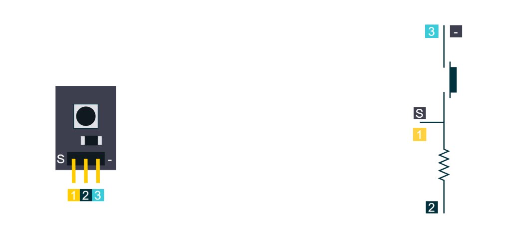
Based on this schematic, we can arrange the connections such that the button is configured as either active high or active low. For this series of exercises, we will connect the button as active high. So the connection will be :
- Pin 1 or S of the KY-004 to 3.3V of the SDP-K1
- Pin 2 (no name) of the KY-004 to GND of the SDP-K1
- pin 3 or – of the KY-004 to D2 of the SDP-K1 that happens to be the GPIO PG7 of the STM32F4
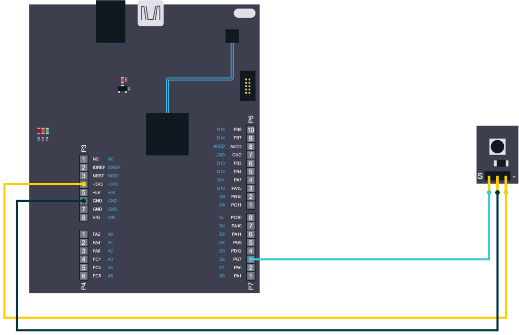
Before diving into the exercises, it is important to note that this button does not include an RC filter for debouncing but is equipped with a pull-down resistor.
Exercise 1: Polling the button status
We need to develop a program that monitors a digital input connected to the external button and performs an action based on the input line state. More precisely the program will turn on the green LED on the SDP-K1 when the button is pressed and turn the LED off when the button is released. The exercise aims to demonstrate how to take an action based on the state of a digital input, which is a fundamental concept in embedded systems programming.
Solution
To implement this exercise, we need to create a program that continuously monitors the digital input line and performs an action based on its state. This can be accomplished using a thread, which periodically checks the input line and sets the LED accordingly. The thread will ensure that the LED state is always synchronized with the state of the input line.
#include "ch.h"
#include "hal.h"

/* Definition of a line representing the external button. */
#define LINE_EXT_BUTTON             PAL_LINE(GPIOG, 7U)

/* Application entry point. */
int main(void) {

  /* ChibiOS/HAL and ChibiOS/RT initialization. */
  halInit();
  chSysInit();

  /* Setting the button line as digital input without pull resistors. */
  palSetLineMode(LINE_EXT_BUTTON, PAL_MODE_INPUT);

  /* main() thread loop. */
  while (true) {
    if (palReadLine(LINE_EXT_BUTTON) == PAL_HIGH) {
      palSetLine(LINE_LED_GREEN);
    }
    else {
      palClearLine(LINE_LED_GREEN);
    }
    chThdSleepMilliseconds(40);
  }
}
In this ChibiOS code, the line LINE_EXT_BUTTON is an alias for line PG7 where our external button is connected. This line is then set as digital input without pull resistors by calling palSetLineMode. In this specific case, there is no need for a pull resistor as there is already one on the KY-004. However, if the user is using a different breakout board you may need to configure the pin as PAL_MODE_INPUT_PULLUP or PAL_MODE_INPUT_PULLDOWN depending on your connection scheme.
The main loop of the program checks every 40ms the state of the button using palReadLine. Depending on the status of the line the green LED is either turned on or off. In this implementation, the LED is set on when the button is pressed and off when the button is released.
This periodic check of the button status is an example of polling. We have seen similar examples in the article Mastering External Interrupts with ChibiOS PAL: From Polling to Events.
Limitations
Latency
The limitation of this solution arises from the nature of polling itself. The change in the button line is asynchronous to the thread. In other words, we don’t know when the user is going to press the button, but we can be sure that it will not be synchronized with the thread execution. The following figure shows a timing diagram of a hypothetical scenario for the button, where the grey circles represent the moments in which the button status is sampled and the action is taken. The areas marked in red represent the latency between the event and response.
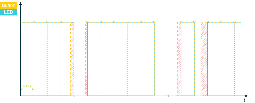
The latency can hence go up to 40 milliseconds in case the button gets pressed exactly at the beginning of the sleep cycle. It can be reduced by speeding up the thread at expense of the CPU load but ultimately the solution would be to go for an interrupt-based approach using the PAL event API as we will show later in another example.
Software debouncing
This solution is not immune to the bouncing effect that can occur when the button is pressed or released. In the event that the input is read during a bouncing event, the LED status may be set incorrectly for 40 milliseconds. While the probability of this occurrence is relatively low, it cannot be entirely ruled out, especially in applications where safety is critical. Therefore, this solution may not be suitable for such applications, and additional measures or different solutions may be necessary to ensure reliable input detection.
Timing
This problem is only applicable in cases where the action, such as changing the status of an LED, takes a negligible amount of time compared to the loop time. However, in scenarios where the action takes significant time to execute, it can result in delays that affect the overall system performance. To illustrate this, consider the following loop:
  while (true) {
    if (palReadLine(LINE_EXT_BUTTON) == PAL_HIGH) {
      /* The following call takes 20ms. */
      myAction1();
    }
    else {
      /* The following call takes 30ms. */
      myAction2();
    }
    chThdSleepMilliseconds(40);
  }
Here we have to separate actions, the first takes 20 milliseconds, the second 30. In this case, the total loop time depends on the status of the button. If the button is pressed, we enter the first statement and it will take 20 + 40 milliseconds before the button is checked again. If we enter the else statement, the loop cycle will last 30 + 40 milliseconds. This is a clear example of where we lost control of the polling cadency and of the latency with it.
Conclusions
Some of the limitations identified in this solution are a result of the problem statement, which was intentionally designed to highlight the challenges of detecting the state of digital inputs. However, upon closer examination of the problem, the primary objective is not to simply detect the button line state, but rather to detect changes in the button line state.
Exercise 2: Edge detection with polling
We need to develop a program that performs a single action when the button is pressed. Specifically, we want to detect the rising edge of the button line and toggle the green LED once for each button press. The exercise aims to demonstrate how to detect line edges using polling in an embedded system.
A dysfunctional solution
The objective of this example is to show the easiest but dysfunctional solution to execute an action when the button is pressed. This solution is actually implemented in all the demos of ChibiOS to trigger the test suite. The idea is to periodically check the status of the button and if it is pressed the action is triggered.
#include "ch.h"
#include "hal.h"

/* Definition of a line representing the external button. */
#define LINE_EXT_BUTTON             PAL_LINE(GPIOG, 7U)

/* Application entry point. */
int main(void) {

  /* ChibiOS/HAL and ChibiOS/RT initialization. */
  halInit();
  chSysInit();

  /* Setting the button line as digital input without pull resistors. */
  palSetLineMode(LINE_EXT_BUTTON, PAL_MODE_INPUT);

  /* main() thread loop. */
  while (true) {
    if (palReadLine(LINE_EXT_BUTTON) == PAL_HIGH) {
      palToggleLine(LINE_LED_GREEN);
    }
    chThdSleepMilliseconds(200);
  }
}
In this ChibiOS code, the button is checked periodically every 200ms using the palToggleLine function, which is an example of polling. We have seen similar examples in the article Mastering External Interrupts with ChibiOS PAL: From Polling to Events.
This implementation has some functional limitations. Ideally, we would want the LED to toggle every time the button is pressed, or in other words, for each rising edge of the LINE_EXT_BUTTON. In reality, if the button is pressed faster than 200 milliseconds, some of these edges may be missed. Moreover, if the button is kept pressed for more than 200 milliseconds, the LED would toggle multiple times.
In summary, this implementation is straightforward but doesn’t achieve the real goal, as it relies on the status of the line rather than detecting the rising edge of the line.
An imperfect yet functional solution
The limitations of the previous solution were a result of the fact that it was designed to poll the input status rather than detect changes in the input state. However, detecting edge changes requires a more sophisticated approach, such as nested conditional statements. If the reader is familiar with digital electronics, they may find it helpful to think of nested conditional statements in software as similar to the implementation of a flip-flop circuit. This is because, in order to access the inner conditional statement, the program must first evaluate the outer condition.
#include "ch.h"
#include "hal.h"

/* Definition of a line representing the external button. */
#define LINE_EXT_BUTTON             PAL_LINE(GPIOG, 7U)

/* Application entry point. */
int main(void) {

  /* ChibiOS/HAL and ChibiOS/RT initialization. */
  halInit();
  chSysInit();

  /* Setting the button line as digital input without pull resistors. */
  palSetLineMode(LINE_EXT_BUTTON, PAL_MODE_INPUT);

  /* main() thread loop. */
  while (true) {

    if (palReadLine(LINE_EXT_BUTTON) == PAL_LOW) {
      /* If we reach this point the line is not pressed. */

      while (palReadLine(LINE_EXT_BUTTON) != PAL_HIGH) {
        /* The execution will be confined to this internal loop
           until the line does not get pressed. */
        chThdSleepMilliseconds(40);
      }

      /* We reach this point only when a transition low to high happened. */
      palToggleLine(LINE_LED_GREEN);
    }
    chThdSleepMilliseconds(10);
  }
}
This code is one of many possible solutions for detecting the rising edge of the button, which triggers the associated action only once upon button press. It is also possible to reverse the logic and detect the falling edge by negating the conditions of the if and the while as shown in our article Mastering External Interrupts with ChibiOS PAL: From Polling to Events. All of the considerations made in that article are also valid for this case. However, we can tailor our approach further to better suit the specific requirements of this exercise.
Limitations
Let us examine a timing diagram for a study case where the button is pressed twice
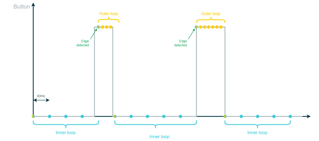
In this diagram, each dot represents a cycle of the thread, and the colors indicate whether we are running the outer loop or the inner loop. The diagram also shows the difference in timing between the inner loop and the outer loop.
Efficiency
Each dot in the timing diagram represents one iteration of the thread and therefore we are having an interrupt and context switch for each dot. This keeps the CPU busy and ultimately consumes system resources. Each detection requires multiple thread loops and it is an indication of an increase in resource consumption. To optimize efficiency, we can count the number of ISR we have to service per button press. This becomes more significant if the button is pressed less frequently. To put this into perspective, consider the button on your preferred smartwatch and imagine that each ISR/Context switch drains some battery charge. In the context of a battery life of several days, each ISR can have a tangible impact.
In general, the limitation of this example in terms of efficiency is still to be attributed to the polling itself which is as said, an imperfect yet functional strategy.
Latency
Similar to the previous code, this solution introduces some delay between the action and reaction, and the maximum delay is influenced by the duration of the inner loop sleep. In this case, the maximum delay can be up to 40 milliseconds, which can occur if the rising edge happens exactly when the sleep of the inner loop is executed.
Failure to detect an edge
If the button is pressed for less than 40 milliseconds, we may not detect the edge at all. However, in this specific case, the dynamics of the button are slower than 40 milliseconds, so this scenario is unlikely to occur.
If we are not dealing with a button and our line can toggle much faster, we can mitigate this risk by reducing the duration of the internal sleep. This would improve the response time but would come at the expense of an increase in the frequency of context switches which means a higher CPU load.
Conclusions
This solution is optimal when we do not have access to hardware that can directly capture external interrupts. Additionally, it provides some protection against bouncing, as there is a minimum delay of 50 milliseconds between two consecutive actions. This delay makes the edge detection insensitive to bouncing that happens within 50 milliseconds of the edge detection.
In the following examples, we will show how to perform the same operation using external interrupts as a mechanism to trigger a callback or regulate the thread’s frequency.
Exercise 3: Edge detection with the event-callback mechanism
We need to develop a program that performs a single action when the button is pressed. Specifically, we want to detect the rising edge of the button line and toggle the green LED once for each button press. This time, however, we are going to use the PAL event API and leverage the external interrupts to tackle the problem of efficiency and latency. More in detail we want to use the event-callback mechanism.
Solution without debouncing
The next code example is going to use the PAL event-callback mechanism and this requires us to enable the associated switch in halconf.h
/*===========================================================================*/
/* PAL driver related settings.                                              */
/*===========================================================================*/
/**
 * @brief   Enables synchronous APIs.
 * @note    Disabling this option saves both code and data space.
 */
#if !defined(PAL_USE_CALLBACKS) || defined(__DOXYGEN__)
#define PAL_USE_CALLBACKS                   TRUE
#endif

/**
 * @brief   Enables synchronous APIs.
 * @note    Disabling this option saves both code and data space.
 */
#if !defined(PAL_USE_WAIT) || defined(__DOXYGEN__)
#define PAL_USE_WAIT                        FALSE
#endif
Our main will look like this
#include "ch.h"
#include "hal.h"

/* Definition of a line representing the external button. */
#define LINE_EXT_BUTTON             PAL_LINE(GPIOG, 7U)

/* Callback associated to the raising edge of the button line. */
static void button_cb(void *arg) {
  (void)arg;

  palToggleLine(LINE_LED_GREEN);
}

/* Application entry point. */
int main(void) {

  /* ChibiOS/HAL and ChibiOS/RT initialization. */
  halInit();
  chSysInit();

  /* Setting the button line as digital input without pull resistors. */
  palSetLineMode(LINE_EXT_BUTTON, PAL_MODE_INPUT);

  /* Enabling the event on the Line for a Rising edge. */
  palEnableLineEvent(LINE_EXT_BUTTON, PAL_EVENT_MODE_RISING_EDGE);

  /* Associating a callback to the Line. */
  palSetLineCallback(LINE_EXT_BUTTON, button_cb, NULL);

  /* main() thread loop. */
  while (true) {
    /* This thread is free for other tasks. */
    chThdSleepMilliseconds(500);
  }
}
Using the PAL API, it is possible to associate a callback function, button_cb(), with the rising edge of the button line. In other words, the callback is associated with the event “button pressed”.
Similar to the previous example, the button line is defined as a digital input without pull resistors. Then, the event for a rising edge on the line is enabled and a callback is associated with the line.
This means that the callback will be called asynchronously every time a rising edge occurs on the button line, without the need for a thread to continuously poll the status of the line. As a result, in this scenario, the main thread loop is free to be used for other tasks and can be left empty.
Solution with debouncing
One potential issue with the previous implementation is that there is no blind time after the edge detection, which can make it susceptible to the problem of button bouncing. Since the callback is executed in the interrupt context, no blocking functions can be called in it as this would impact the scheduling. This means that it is not possible to simply add a sleep function to the callback to artificially stop the detection, as there is no thread involved – only an ISR.
To address this issue, we need to think in terms of interrupts. One solution is to disable the line edge detection in the callback and set a new interrupt to re-enable the line edge detection after a specified amount of time. ChibiOS\RT offers a tool for scheduling callbacks after a specific amount of time, called a virtual timer.
#include "ch.h"
#include "hal.h"

/* Definition of a line representing the external button. */
#define LINE_EXT_BUTTON             PAL_LINE(GPIOG, 7U)

/* Function prototypes needed as the two callbacks call each other.
   there is no way to order the callback without triggering an error. */
static void button_cb(void *arg);
static void vt_cb(virtual_timer_t *vtp, void *p);

/*===========================================================================*/
/* VT related code.                                                          */
/*===========================================================================*/

/* Virtual timer. */
static virtual_timer_t vt;

/* Callback of the virtual timer. */
static void vt_cb(virtual_timer_t *vtp, void *p) {

  (void)vtp;
  (void)p;

  chSysLockFromISR();

  /* Enabling the event and associating the callback. */
  palEnableLineEventI(LINE_EXT_BUTTON, PAL_EVENT_MODE_RISING_EDGE);
  palSetLineCallbackI(LINE_EXT_BUTTON, button_cb, NULL);

  chSysUnlockFromISR();
}

/*===========================================================================*/
/* Button related code.                                                      */
/*===========================================================================*/

/* Callback associated to the raising edge of the button line. */
static void button_cb(void *arg) {
  (void)arg;

  palToggleLine(LINE_LED_GREEN);

  chSysLockFromISR();

  /* Disabling the event on the line and setting a timer to
     re-enable it. */
  palDisableLineEventI(LINE_EXT_BUTTON);

  /* Arming the VT timer to re-enable the event in 50ms. */
  chVTResetI(&vt);
  chVTDoSetI(&vt, TIME_MS2I(50), vt_cb, NULL);

  chSysUnlockFromISR();
}

/*===========================================================================*/
/* Application entry point.                                                  */
/*===========================================================================*/

int main(void) {

  /* ChibiOS/HAL and ChibiOS/RT initialization. */
  halInit();
  chSysInit();

  /* Initializing the virtual timer. */
  chVTObjectInit(&vt);

  /* Setting the button line as digital input without pull resistors. */
  palSetLineMode(LINE_EXT_BUTTON, PAL_MODE_INPUT);

  /* Enabling the event and associating the callback. */
  palEnableLineEvent(LINE_EXT_BUTTON, PAL_EVENT_MODE_RISING_EDGE);
  palSetLineCallback(LINE_EXT_BUTTON, button_cb, NULL);

  /* main() thread loop. */
  while (true) {
    /* This thread is free for other tasks. */
    chThdSleepMilliseconds(500);
  }
}
Let’s analyze the differences between this solution and the previous one. In this implementation, we introduce a new object called vt, which represents the virtual timer. This object is initialized once in the main function.
The callback function associated with the line detection is also different in this case, as it now needs to disable the line event and activate the virtual timer. The functions used to do this are considered time-critical, which means that we need to prevent any interrupts from blocking their execution. This is achieved by creating a critical zone.
static void my_isr(void) {

  chSysLockFromISR();

  /* I-Locked critical zone. The code in here
     cannot be interrupted. */

  chSysUnlockFromISR();
}
When we activate the virtual timer, we specify which callback function should be executed and after how long. In this case, the callback vt_cb is set to be executed after 50 milliseconds, and NULL represents the parameter that we pass to this callback.
chVTDoSetI(&vt, TIME_MS2I(50), vt_cb, NULL);
The callback function associated with the virtual timer performs the necessary steps to re-enable the line edge detection and re-associate the callback function with the line.
Notes about the event-callback approach
The reason why we had to use the virtual timer instead of placing a sleep in the callback of PAL is that, once again, this function is executed by an ISR of the external interrupt. It is not possible to place blocking functions in an ISR, as this will block the entire system until the ISR is terminated. In the case of the ARM architecture, where Nested Interrupts are possible, higher priority ISR will still be able to preempt our callback, but the entire scheduling will be compromised.
To summarize, any function that typically blocks a thread cannot be executed in an ISR context, and any function of ChibiOS called in this context needs to be I-Class or X-Class.
Exercise 4: Edge detection with the event-wait mechanism
We need to develop a program that performs a single action when the button is pressed. Specifically, we want to detect the rising edge of the button line and toggle the green LED once for each button press using the Event-Wait mechanism.
Solution
The next code example is going to use the PAL Event-Waitmechanism and this requires us to enable the associated switch in halconf.h
/*===========================================================================*/
/* PAL driver related settings.                                              */
/*===========================================================================*/

/**
 * @brief   Enables synchronous APIs.
 * @note    Disabling this option saves both code and data space.
 */
#if !defined(PAL_USE_CALLBACKS) || defined(__DOXYGEN__)
#define PAL_USE_CALLBACKS                   FALSE
#endif

/**
 * @brief   Enables synchronous APIs.
 * @note    Disabling this option saves both code and data space.
 */
#if !defined(PAL_USE_WAIT) || defined(__DOXYGEN__)
#define PAL_USE_WAIT                        TRUE
#endif
The following code is the suggested solution.
#include "ch.h"
#include "hal.h"

/* Definition of a line representing the external button. */
#define LINE_EXT_BUTTON             PAL_LINE(GPIOG, 7U)

/* Application entry point. */
int main(void) {

  /* ChibiOS/HAL and ChibiOS/RT initialization. */
  halInit();
  chSysInit();

  /* Setting the button line as digital input without pull resistors. */
  palSetLineMode(LINE_EXT_BUTTON, PAL_MODE_INPUT);

  /* Enabling the event on the Line for a Rising edge. */
  palEnableLineEvent(LINE_EXT_BUTTON, PAL_EVENT_MODE_RISING_EDGE);

  /* main() thread loop. */
  while (true) {
    /* Waiting for the even to happen. */
    palWaitLineTimeout(LINE_EXT_BUTTON, TIME_INFINITE);

    /* Our action. */
    palToggleLine(LINE_LED_GREEN);

    /* Debouncing. */
    chThdSleepMilliseconds(50);
  }
}
In this implementation, we are utilizing the event to synchronize a thread. The main thread is waiting indefinitely for the event to occur, and when it does, the desired action is executed. As we are now in a thread context, we can use the chThdSleepMilliseconds() function to introduce a delay of 50 milliseconds to the thread and thereby implement the debouncing. However, since the thread is now subject to the scheduling rule, we need to be cautious in selecting the priority of the thread to avoid any potential latency in our response to the event.
Conclusions
In this article, we have explored various approaches to detecting button presses in embedded systems using the ChibiOS/RT operating system and the ChibiOS/HAL library. We started with a basic solution that relied on status polling and subsequently moved on to more advanced methods that utilized external interrupts and event-driven programming to provide more efficient and reliable button detection. We also discussed the issues of button bouncing and debouncing, and how they can impact the accuracy of the detection.
We would like to add that when it comes to software debouncing, the optimal timing ultimately depends on the mechanics of the button and the specific use case. In the appendix of this article, we spend some more words about how to optimize the software debouncing for the KY-004.
While each of these solutions has its pros and cons, the best approach largely depends on the specific requirements of the application. Therefore, it’s essential to carefully analyze the needs of the system and select the most appropriate method for detecting button presses.
Appendix A: Determining the size of a pull resistor for a button
We have previously discussed pull resistors and how to determine their size in our article, Fundamentals of Digital Circuitry. In this section, we aim to briefly recap the concepts explained there and tailor the theory to our specific case. In general:
- The pull resistor can be connected to either the high side (pull-up resistor) or the low side (pull-down resistor).
- The pull resistor influences the speed of the transient depending on its placement, which means it affects the rising edge when connected as a pull-up resistor on the high side and the falling edge when connected as a pull-down resistor on the low side.
- A larger resistor limits the current flow and slows down the transient, often referred to as a “weak” pull resistor. Conversely, a smaller resistor allows for greater current flow and faster transient response and it is often referred to as a “strong” pull resistor.
- The terms weak and strong are a reference to the resistance that pull-up and pull-down resistors provide during the opposite transient. For example, a strong pull-up resistor can accelerate the rising edge transient, but it may have a negative impact on the falling edge transient. This is because the current flowing through the resistor resists the change in the opposite direction.
When selecting a pull resistor for a button, a weak resistor is typically sufficient. This is because button dynamics are relatively slow compared to the speed of electronic components. When considering how fast a human can press a button, we are looking at a time range of around 100ms. Consequently, a transient on the order of 1ms is more than adequate for most practical applications. The model we are using for our calculations is the following.
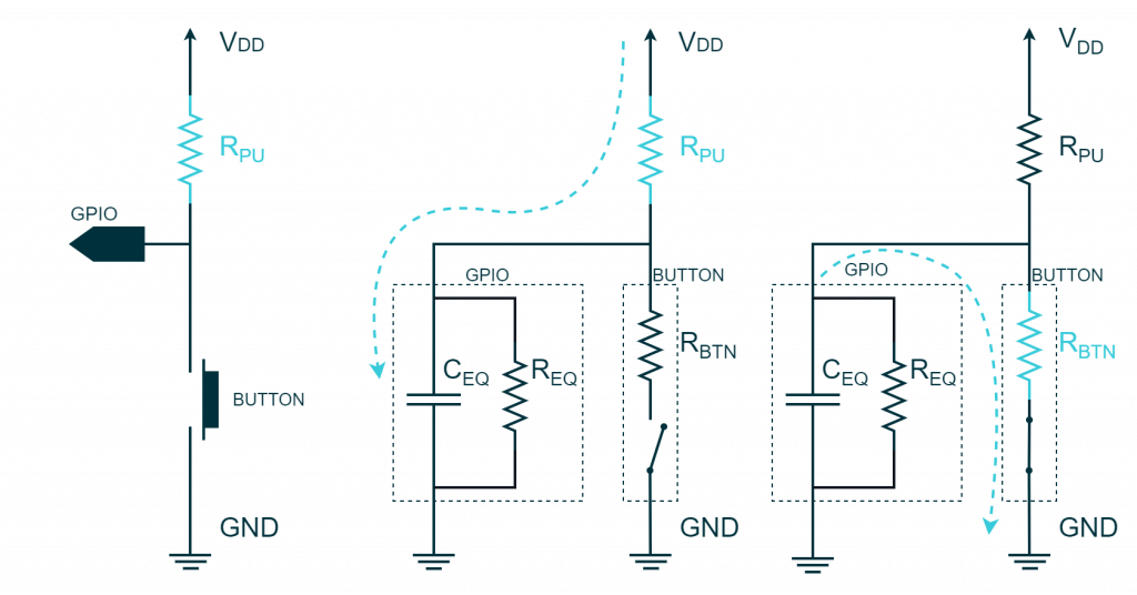
When examining the rising edge, the voltage on the capacitor CEQ represents the voltage read by the GPIO and it follows the following formula

The capacitor charges through the pull-up resistor. It takes 5RC (i.e. 5 time-constants) for the voltage level to reach 99% of the total transient value. Considering an equivalent capacitance of 50pF and a weak 400kΩ pull-up resistor, we still achieve a transient time that is acceptable for most applications.
| RPU [Ω] | 95% transient (3 RC) [uS] | 99% transient (5 RC) [uS] |
|---|---|---|
| 500 | 0.075 | 0.125 |
| 400k | 60 | 100 |
A similar analysis applies to an active high button, where the task is to choose the appropriate size of a pull-down resistor. In this case, the pull-down resistor influences the falling edge transition. However, the underlying calculations remain valid. We encourage readers to refer to the previously mentioned article for a deeper understanding of the equivalent circuit presented and a more detailed analysis of real-world scenarios.
Appendix B: Button bouncing and debouncing techniques
Push-buttons and other mechanical switches are commonly affected by a problem known as button bouncing. This occurs when a button is pressed or released, and its contacts do not immediately change states. Instead, the contacts may close and break several times in a short period due to mechanical vibrations. This creates a series of rapid high and low transitions causing erroneous behavior in the system.
To better understand the issue, consider the following scope shot of our KY-004 board connected in active high logic. We can see that in this specific case, there are multiple rising edges instead of a single, steep edge. This happens because the mechanical vibrations caused by the button press cause the contact to close and break multiple times.
This makes it looks like the button has been pressed and released multiple time and can lead to misbehavior of our application. However, this issue can be mitigated using two main approaches: hardware debouncing and software debouncing.
Hardware debouncing
Hardware debouncing involves adding external components to the button circuit to filter out the bouncing effect. Common hardware debouncing techniques include the usage of an RC Filter: Connecting a resistor and a capacitor in series between the button and the input pin creates an RC filter. When the button is pressed or released, the capacitor charges or discharges through the resistor, smoothing out the voltage transitions and suppressing the bouncing effect.
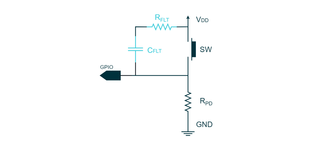
To analyze this circuit we are going to make use once again of the First-order RC circuit. This circuit is explained thoroughly in Appendix A of the article Fundamental of Digital Circuitry.
Let us assign some values to the components and analyze how this circuit works. For example, let us consider CFLT to be 10nF, RFLT 100Ω, and RPD 220kΩ. We will start by analyzing the rising edge, assuming that the button has remained unpressed long enough for all transients to subside. In this case, the GPIO line is pulled down to 0V, and the capacitor needs to be charged to 5V. When the button is pressed, the GPIO gets connected to VDD, and the capacitor discharges through RFLT. The GPIO is not affected by this transient since it is directly shorted to VDD. However, if we examine the transient, it takes 30us for the capacitor to reach 95% of the total voltage change.
Upon releasing the button, the line will go down, but this time the transient will influence the timing. The capacitor needs to reach VDD so that the voltage level on the GPIO line is 0V. In this specific case, the time constant is CFLT(RPD + RFTL), which is approximately equal to CFLT*RPD. This transient takes 66ms to reach 95% of the total voltage change.
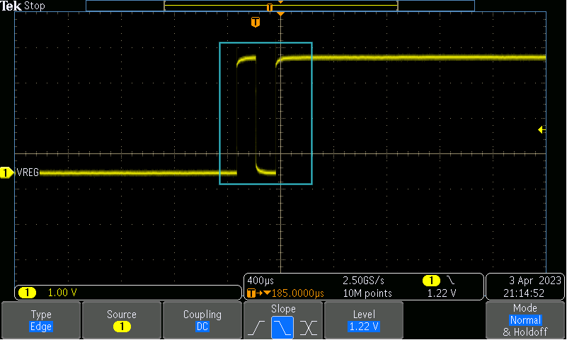
If we examine the bouncing dynamics in our oscilloscope capture, we can see that the bouncing caused the line to unexpectedly drop for around 200us. This behavior is negligible compared to a transient in the order of 66ms. In summary, with such a circuit, we would not have observed a dip in our oscilloscope capture at all.
Software debouncing
The second solution to the bouncing issue is to use delays in software after the detection of the first edge. This can be done in many different ways but the typical solution is to stop the polling or ignore interrupts for a specific amount of time. When it comes to software debouncing, the optimal timing ultimately depends on the mechanics of the button and the specific use case. Although hardware debouncing is a more reliable solution, it may not be an option if the button is already mounted on an evaluation kit or a breakout board and hence we need to rely on software to address the issue.
Optimizing the debouncing for the KY-004
In the case of the KY-004, there is no hardware debouncing implemented and the push buttons used in this kit are known to be cheaply made.
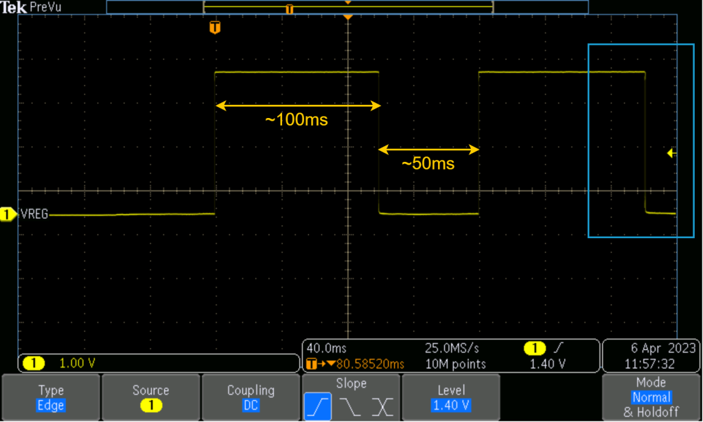
In our previous event-based solution, we chose a blind time of 50 milliseconds to ignore any interrupt that occurs within 50 milliseconds after the first one to account for the bouncing effect. However, we found that false detections still occurred in some cases, particularly when rapidly clicking on the button. This is likely due to the internal contact plate vibrating from the previous hit. To illustrate this issue, we have included a scope shot of two clicks on the KY-004 in rapid succession that appear to be affected by the bouncing effect. At a first glance, everything looked normal even if the LED toggled three times during this sequence.
But upon closer inspection of the last falling edge, it appears the corner are blurry. So I zoomed in further and to my surprise, it looks like it was doing the Macarena dance. Who knew that buttons had rhythm?
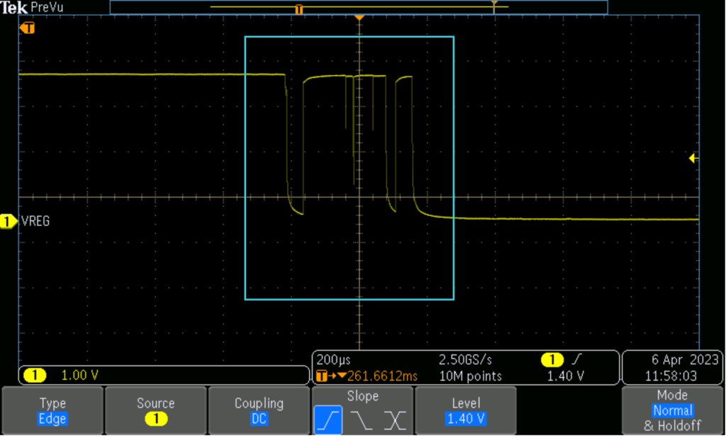
The original choice of 50 milliseconds for the blind time was not sufficient, as observed during testing. In selecting a blind time, it is important to ensure that it is long enough to cover both edges, but not so long that it masks the second edge. Therefore, the chosen blind time was increased to 110 milliseconds. It is possible that this solution may not work if the button is held down for an extended period, but this issue typically occurs only when the button is pressed rapidly, causing vibration on the internal plate. Slowing down the button press should prevent this issue. However, as previously mentioned, hardware debouncing is always the preferred option over software solutions when available.
Hello
The information provided was a bit incomprehensible due to the programming language other than the HAL library
But anyway, useful content was provided
Hello Esi,
thanks for the feedback. If you could clarify which part is unclear, we may try to review the article and improve its readability.
Thanks Rocco, it is the most complete explanation on methods to avoid bouncing I’ve ever seen. I wish I knew it two years ago, as I had to discover this by myself. And Chibios it’s a real RTOS, not as the HAL library that is only an implementation of STM32 routines
Hi Joaquin,
Thanks for commenting. I have to say HAL is much more than a library for STM32: it is a well designed API that can potentially work on every MCU. Furthermore, it is perfectly designed for real time applications.
However, I do agree with you: RT is the the core of the ChibiOS project.
You should really take a look at this article
Is ChibiOS an RTOS or a HAL? Understanding the full picture