
Mikroe Clicker 2 for STM32 and STLink v2
Introduction
In this tutorial we are going to see how to connect a STLink v2 debugger to a Clicker 2 for STM32 enabling users to do debugging which could be very useful in development phases. A debugger is a computer program which is used to test and debug another program usually named Target.
In embedded things are slightly different since the code is executed on an external MCU and it is required an interface Computer-MCU. In this case the Target is the MCU and a debugger is composed by the ensemble of a hardware and a software tool. Nonetheless, when the majority of people is talking about debugger,they are referring only to the hardware part.
A debugger allows the connection to a Target enabling the Host to load a firmware on it managing its code execution, allowing the inspection of its registers and much more. To do this, it uses some specific commands that usually depend on the MCU architecture: this means that there are specific debuggers for specific MCUs. The STLink v2 is a low cost debugger supporting both STM32 and STM8. In what follows we are going to use OpenOCD, an open source debugging software largely used in ChibiStudio since it is a reliable solution for debugging.
The JTAG/SWD connector
Joint Test Action Group
The JTAG also know as Joint Test Action Group is an electronics industry association founded in 1985 for developing standards for on-chip instrumentation in electronic design automation as an alternative to simulation tools. Today, the JTAG is a standard used by many semiconductor chip manufacturers which have extended it with commands to provide vendor-specific features.
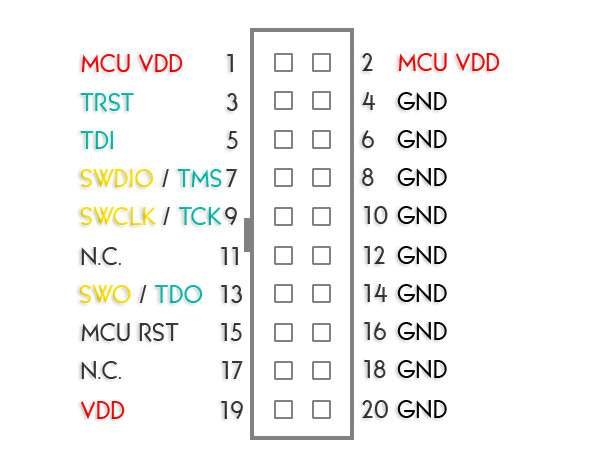
There are different JTAG connectors but almost everyone contains these PINs:
- TDI, or Test Data In;
- TDO, or Test Data Out;
- TCK, or Test Clock;
- TMS, or Test Mode Select;
- TRST, or Test Reset which is optional.
As example in Fig.1 we can see a ARM 20-PIN JTAG connector with the pin-map. The connector shown in figure is the same available on the STLink v2 and we are going to use it and certain PINs (the ones orange and azure) have a dual function.
ARM Serial Wire Debug
The SWD also know as Serial Wire Debug is an interface developed by ARM and is an alternative to JTAG for these packages with limited PINs. SWD uses a standard bi-directional wire protocol defined in the ARM Debug Interface v5.
SWD replaces the 5-pin JTAG port with a clock + single bi-directional data PIN having data rate up to 4 MB/s at 50 MHz. Additional features could be achieved using one more PIN named TRACESWO. On JTAG devices with SWD capability:
- TMS, is used as SWDIO;
- TCK, is used as SWCLK;
- TDO, is used as SWO.
Connecting the STLink v2

The STLink v2 supports both JTAG and SWD interfaces but STM32 uses SWD only. Let’s see how to connect the STLink to our Clicker 2 using some Dupont wires. The schematic of STLink v2 JTAG/SWD connector is shown in Fig.1. Opening the Clicker 2 For STM32 User Manual we can notice that this board uses a ARM 10 PIN JTAG Connector which is shown in Fig.2.
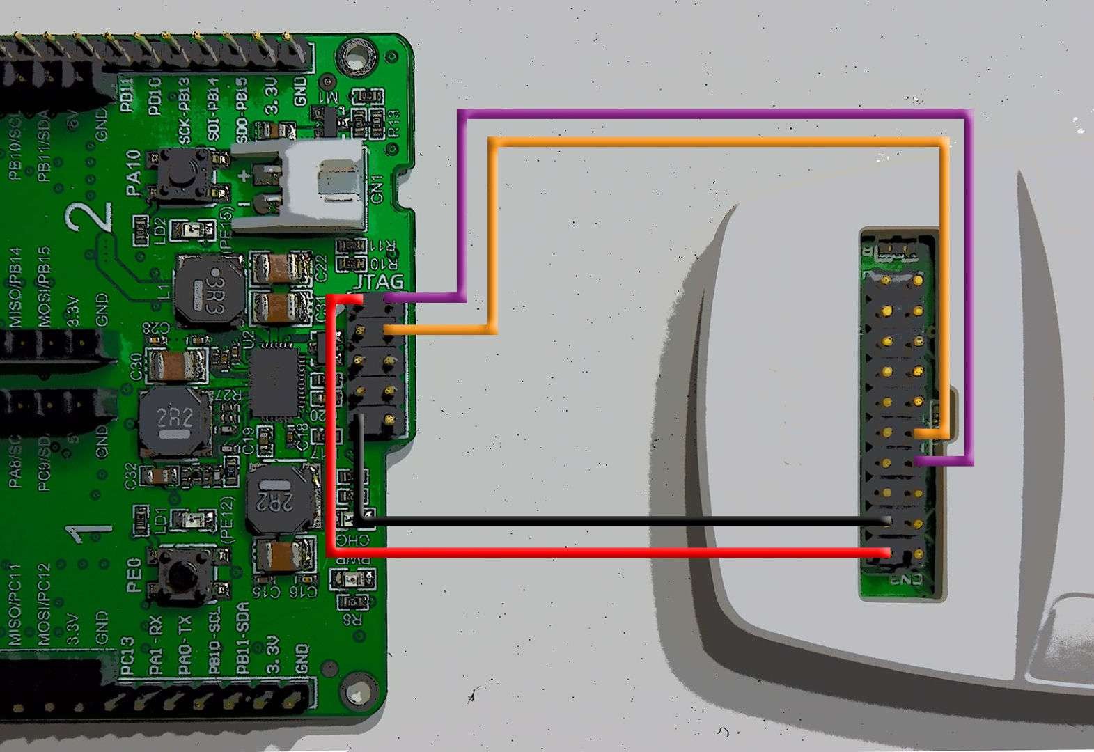
We just need to connect 4 wire between STLink and Clicker 2 to establish a communication. A feasible connection (STLink to Clicker) could be:
- SWDIO, 2 to 1;
- SWCLK, 4 to 9;
- VCC, 7 to 2 ;
- GND, 9 to 4.
How to unlock and erase Flash Memory
The embedded flash memory of the STM32F4 has the Read/Write protection and it can be activated acting mainly on the FLASH_CR register. It seems like the latest version of mikroe Bootloader enables this protection so we need to variate a little bit the flash and run procedure to unlock the flash.
We will use a command prompt like MSYS2 (or even Windows CMD) and OpenOCD. Note that we already have a copy of OpenOCD inside ChibiStudio and that we have already used MSYS2 in this article.
Taking stock of the situation, we will launch OpenOCD making some additional operations and we will perform a classical Flash and Run procedure. We need for a working project for Clicker 2 and we will use that from the previous tutorial. First step would be launching the OpenOCD and we can do this directly from ChibiStudio, into the External Tools menu choosing “OpenOCD on ST-Link V2 (prompts for .cfg target configuration)” and selecting the configuration file “C:\ChibiStudio\tools\openocd\scripts\target\stm32f4x.cfg”.
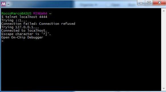
At this point, keeping ChibiStudio opened, we have to launch the MSYS2 bash. We will use it to force the memory unlock launching some OpenOCD commands through Telnet (See Fig.4). First command establish a Telnet communication on the localhost on port 4444:
telnet localhost 4444
Once the communication has been established we have to issue a halt command to the Target to break the program execution.
reset halt
Now we can use the official unlock procedure for STM32. Don’t worry about the command name because the flash controller is the same in both STM32F2 and STM32F4. This procedure can take some seconds and is completed only when bash replies with the sentence “stm32f2x unlocked”: be patient and wait.
stm32f2x unlock 0
Push the reset button on the board before to proceed. Now we have to rewrite the value of the FLASH_OPTCR field into the FLASH_CR register to unlock the memory. This requires a special procedure described into the STM32F4 Reference Manual. Note that these commands will not produce any output on the command line:
mww 0x40023C08 0x08192A3B; mww 0x40023C08 0x4C5D6E7F; mww 0x40023C14 0x0fffaaed
Now we can come back to ChibiStudio and perform the flash and run procedure which will be successful.
Restoring the mikroe Bootloader
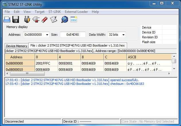
To restore the mikroe Bootloader we need to download it from the mikroe website. It is included with the package of the USB HID Bootloader under the folder “firmware”. It is a simple .hex file that could be flashed using both OpenOCD or ST Link Utility.
Great. Thank You.
Need your help please!
I have been following your instructions as above but can`t connect with STM32F429discovery
$ telnet localhost 4444Trying ::1...
Connection failed: Connection refused
Trying 127.0.0.1...
telnet: Unable to connect to remote host: Connection refused
I have tried through chibistudio
Open On-Chip Debugger 0.10.0+dev-00161-g1725abc3c (2017-06-24-20:22)Licensed under GNU GPL v2
For bug reports, read
http://openocd.org/doc/doxygen/bugs.html
Warn : Interface already configured, ignoring
Error: already specified hl_layout stlink
Info : The selected transport took over low-level target control. The results might differ compared to plain JTAG/SWD
adapter speed: 2000 kHz
adapter_nsrst_delay: 100
none separate
srst_only separate srst_nogate srst_open_drain connect_deassert_srst
Info : Unable to match requested speed 2000 kHz, using 1800 kHz
Info : Unable to match requested speed 2000 kHz, using 1800 kHz
Info : clock speed 1800 kHz
Error: open failed
in procedure 'init'
in procedure 'ocd_bouncer'
Thanks
I am sorry but I am missing the point. Are you using an external debugger on STM32F429 Discovery? Why? Discovery kits have embed STLink.
Great page. One detail: “TDI, is used as SWO” sounds suspicious. Thank you!
Thanks Someone,
fixed
Great article! It saved me a lot of time today. Thanks for sharing.