Registers and bitmasks
Introduction
Bitmasking is a powerful technique used in computer science that leverages bitwise operators and bitmasks to selectively modify specific bits or bitfields within a larger data structure, such as a register or memory location. By using bitwise operations such as AND, OR, XOR, NOT, and bit shifting, we can extract, modify, or combine individual bits within the data structure. Bitwise operators and bitmasks are essential concepts in low-level programming, embedded systems, and digital signal processing, allowing us to control hardware devices, set and clear flags, and perform bitwise operations on data.
In this article, we will explore the basics of bitwise operators and bitmasks, demonstrating how to use them to manipulate register values with ease. We will cover the bitwise AND, OR, XOR, NOT, and shift operators, and show you how to use them to mask or invert specific bits within a register. Additionally, we will discuss how to define bitmasks in a more elegant and clear way, allowing for the simple composition of register values.
The goal of this article is to give you a solid understanding of the power of bitmasking and be able to apply it to your own projects and programs.
Registers and bitfields
A register is a small amount of fast memory used to store and manipulate data during program execution. Registers can be found in different components of a computer system, such as the CPU, microcontrollers, or remote devices.
- CPU registers are a type of register found within the CPU of a computer. They are designed to provide quick access to data and instructions needed by the CPU during program execution. CPU registers are typically used to store data that is used frequently or temporarily, such as arithmetic operands, pointers, and status flags. These registers are accessible using assembly instructions.
- Microcontroller’s peripheral registers are used to control the behavior and settings of the microcontroller’s peripherals, such as timers, serial ports, and analog-to-digital converters. These registers are mirrored at specific memory locations.
- Remote registers are registers found in remote devices such as a sensor or actuators. These registers are accessible over communication protocols such as SPI (Serial Peripheral Interface) or I2C (Inter-Integrated Circuit). These registers are used to configure the remote device but also to exchange data between the remote device and the host computer or microcontroller.
Interacting with a machine, its peripherals, or remote devices typically involves reading, modifying, and writing one or more registers. Registers have typically a fixed-length size with lengths of 8, 16, 32, or 64 bits, depending on the architecture and other constraints. Data in registers is often organized into bitfields, which are sets of contiguous bits that represent independent values or settings. Bitfields enable programmers to efficiently pack multiple values into a single register. For example, the following picture is the description of one of the registers of the accelerometer ADXL355
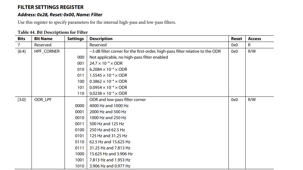
Upon analyzing the description, we can observe that the Filter is an 8-bit register with three bitfields:
- ODR_LPF: This bitfield spans from bit 0 to bit 3, making it 4-bit wide. It can have 16 different values, out of which 11 are meaningful and 5 are reserved.
- HPF_CORNER: This bitfield spans from bit 4 to bit 6, making it a 3-bit word. It can have 8 different values, out of which 7 are meaningful.
- Reserved: Bit 7 is most likely an unpopulated bitfield that needs to be left at its default value which is 0.
Since configuration fields are often packed together to optimize memory usage, a common issue in embedded programming is how to modify a small portion of the register while leaving the remaining bits unchanged. For instance, consider the scenario where we want to modify the HPF_CORNER bitfield while keeping the other bits in the Filter register unaltered.
Modifying bitfields with bitmasking
Bitmasking is a common technique that leverages bitwise operators to selectively modify specific bits or bitfields within a larger data structure, such as a register or memory location. Using bitwise operations such as AND, OR, XOR, NOT, and bit shifting it is possible to extract, modify, or combine individual bits within the data structure.
The term bitmask refers to the binary pattern used as a mask to select or modify specific bits within the data structure.
In the following section, we will discuss the most commonly used bitmasking operations. These operations involve reading the value of a register, masking certain bitfields, and then writing the new value back to the register, therefore is commonly referred to as a read-modify-write operation.
We assume that the reader is familiar with bitwise operations. Appendix A provides a recap of this topic for those who need it.
Bitmasking bits to 1
This operation uses the principle that the OR operator returns 1 if any of its inputs are 1. If we indeed explore the OR better we can notice that his truth table can be revised as
| A | B | A OR B |
|---|---|---|
| X | 0 | X |
| X | 1 | 1 |
In this truth table, we have left the value of one input (A) unspecified (represented by X, which can be either 1 or 0). We can observe that the output of the OR operation depends solely on the value of the other input (B). If B is 1, then the output of the OR operation is 1, regardless of the value of A. However, if B is 0, then the output of the OR operation is equal to A, or in other words, the value of A is propagated to the output.
Therefore, should come as no surprise that the Bitwise OR (denoted by the symbol |)can be used to mask bitfields to 1 as shown in the following example
/* Example #1, masking the first bit to 1. */
  0bXXXXXXXX |
  0b00000001
 -------------
  0bXXXXXXX1


/* Example #2, masking the fifth bit to 1. */
  0bXXXXXXXX |
  0b00010000
 -------------
  0bXXX1XXXX


/* Example #3, masking the forth and fifth bit to 1. */
  0bXXXXXXXX |
  0b00011000
 -------------
  0bXXX11XXX
If you are not familiar with this operator, you may want to scroll down to the appendix of this article where all the bitwise operators are described with plenty of examples.
Once more X represents a non-specified bit that can be 0 or 1. Let us consider the following register that is used to configure the SPI peripheral of an STM32F4
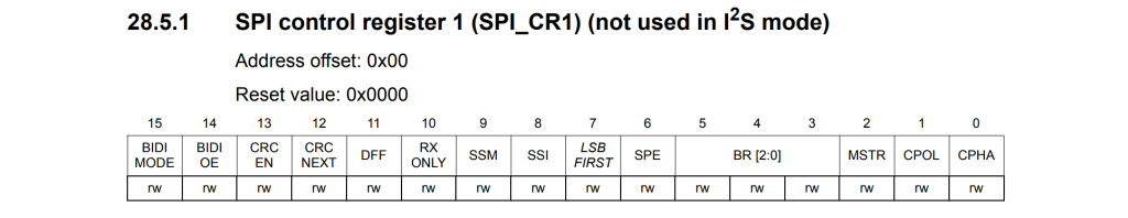
Let us assume that we want to write 7 (i.e. 0b111) in the bitfield BR, and set CPHA to 1 leaving all the other bitfields unchanged and set. Then we may write
/* The following line reads the SPIx_CR1 register and stores it in cr1_val. */
uint16_t cr1_val = readRegister(SPIx_CR1);

/* Overwriting the BR and CPHA bitfields with all ones. Note that 0x39 in binary is
   0b111001 that is the mask of BR | CPHA. */
cr1_val = cr1_val | 0x39;

/* Rewiting the register with the new value. */
writeRegister(SPIx_CR1, cr1_val);
The problem with using hardcoded numbers, such as 0x39, is that they can be scattered throughout the code and make the entire application difficult to read and understand. When encountering a magic number (as they are often called in technical jargon) without proper context or explanation, it can be challenging to comprehend what is happening in the code.
Bitmasks can make the code more user-friendly and maintainable. By using bitmasks, the purpose and meaning of each bit or bitfield can be clearly defined and labeled, making it easier for others to understand the code and its functionality. For example, the following bitmasks are defined in the CMSIS header that ST provides together with the STM32
/*******************  Bit definition for SPI_CR1 register  ********************/
#define SPI_CR1_CPHA_Pos            (0U)
#define SPI_CR1_CPHA_Msk            (0x1U << SPI_CR1_CPHA_Pos)                 /*!< 0x00000001 */
#define SPI_CR1_CPHA                SPI_CR1_CPHA_Msk                           /*!<Clock Phase      */
#define SPI_CR1_CPOL_Pos            (1U)
#define SPI_CR1_CPOL_Msk            (0x1U << SPI_CR1_CPOL_Pos)                 /*!< 0x00000002 */
#define SPI_CR1_CPOL                SPI_CR1_CPOL_Msk                           /*!<Clock Polarity   */
#define SPI_CR1_MSTR_Pos            (2U)
#define SPI_CR1_MSTR_Msk            (0x1U << SPI_CR1_MSTR_Pos)                 /*!< 0x00000004 */
#define SPI_CR1_MSTR                SPI_CR1_MSTR_Msk                           /*!<Master Selection       */

#define SPI_CR1_BR_Pos              (3U)
#define SPI_CR1_BR_Msk              (0x7U << SPI_CR1_BR_Pos)                   /*!< 0x00000038 */
#define SPI_CR1_BR                  SPI_CR1_BR_Msk                             /*!<BR[2:0] bits (Baud Rate Control)   */
#define SPI_CR1_BR_0                (0x1U << SPI_CR1_BR_Pos)                   /*!< 0x00000008 */
#define SPI_CR1_BR_1                (0x2U << SPI_CR1_BR_Pos)                   /*!< 0x00000010 */
#define SPI_CR1_BR_2                (0x4U << SPI_CR1_BR_Pos)                   /*!< 0x00000020 */

#define SPI_CR1_SPE_Pos             (6U)
#define SPI_CR1_SPE_Msk             (0x1U << SPI_CR1_SPE_Pos)                  /*!< 0x00000040 */
#define SPI_CR1_SPE                 SPI_CR1_SPE_Msk                            /*!<SPI Enable                          */
#define SPI_CR1_LSBFIRST_Pos        (7U)
#define SPI_CR1_LSBFIRST_Msk        (0x1U << SPI_CR1_LSBFIRST_Pos)             /*!< 0x00000080 */
#define SPI_CR1_LSBFIRST            SPI_CR1_LSBFIRST_Msk                       /*!<Frame Format                        */
#define SPI_CR1_SSI_Pos             (8U)
#define SPI_CR1_SSI_Msk             (0x1U << SPI_CR1_SSI_Pos)                  /*!< 0x00000100 */
#define SPI_CR1_SSI                 SPI_CR1_SSI_Msk                            /*!<Internal slave select               */
#define SPI_CR1_SSM_Pos             (9U)
#define SPI_CR1_SSM_Msk             (0x1U << SPI_CR1_SSM_Pos)                  /*!< 0x00000200 */
#define SPI_CR1_SSM                 SPI_CR1_SSM_Msk                            /*!<Software slave management           */
#define SPI_CR1_RXONLY_Pos          (10U)
#define SPI_CR1_RXONLY_Msk          (0x1U << SPI_CR1_RXONLY_Pos)               /*!< 0x00000400 */
#define SPI_CR1_RXONLY              SPI_CR1_RXONLY_Msk                         /*!<Receive only                        */
#define SPI_CR1_DFF_Pos             (11U)
#define SPI_CR1_DFF_Msk             (0x1U << SPI_CR1_DFF_Pos)                  /*!< 0x00000800 */
#define SPI_CR1_DFF                 SPI_CR1_DFF_Msk                            /*!<Data Frame Format                   */
#define SPI_CR1_CRCNEXT_Pos         (12U)
#define SPI_CR1_CRCNEXT_Msk         (0x1U << SPI_CR1_CRCNEXT_Pos)              /*!< 0x00001000 */
#define SPI_CR1_CRCNEXT             SPI_CR1_CRCNEXT_Msk                        /*!<Transmit CRC next                   */
#define SPI_CR1_CRCEN_Pos           (13U)
#define SPI_CR1_CRCEN_Msk           (0x1U << SPI_CR1_CRCEN_Pos)                /*!< 0x00002000 */
#define SPI_CR1_CRCEN               SPI_CR1_CRCEN_Msk                          /*!<Hardware CRC calculation enable     */
#define SPI_CR1_BIDIOE_Pos          (14U)
#define SPI_CR1_BIDIOE_Msk          (0x1U << SPI_CR1_BIDIOE_Pos)               /*!< 0x00004000 */
#define SPI_CR1_BIDIOE              SPI_CR1_BIDIOE_Msk                         /*!<Output enable in bidirectional mode */
#define SPI_CR1_BIDIMODE_Pos        (15U)
#define SPI_CR1_BIDIMODE_Msk        (0x1U << SPI_CR1_BIDIMODE_Pos)             /*!< 0x00008000 */
#define SPI_CR1_BIDIMODE            SPI_CR1_BIDIMODE_Msk                       /*!<Bidirectional data mode enable      */
This C code defines the bit positions and masks for all the bitfields of the SPI_CR1:
Posis the position of the least significant bit (LSB) for a specific bitfield in the register.Mskis the bitmask to isolate a specific field in the register.
Each field in the SPI_CR1 register has a corresponding *_Pos and *_Msk definition. The *_Pos defines the starting bit position of the field, while *_Msk is used to isolate the field from other bits in the register.
Let’s take the SPI_CR1_BR field as an example:
SPI_CR1_BR_Posis the position of the least significant bit (LSB) of the Baud Rate Control field in SPI_CR1 (bit 3).SPI_CR1_BR_Mskis the bitmask for the Baud Rate Control field (0x7 << 3 = 0x00000038).
Additionally, we have a definition per each one of the bits of this bitfield:
SPI_CR1_BR_0that is the first bit in position (0x1 << 3 = 0x00000008)SPI_CR1_BR_1that is the first bit in position (0x2 << 3 = 0x00000010)SPI_CR1_BR_2that is the first bit in position (0x4 << 3 = 0x00000020)
And a cumulative definition that indicates all the bits set to one SPI_CR1_BR. This bitmask is 0x7 in position and is identical to SPI_CR1_BR_Msk.
So if we leverage this concept and we look back to our previous example we may use the mask SPI_CR1_BR and SPI_CR1_CPHA to make our previous example more elegant and readable. So the code we had before that was
/* The following line reads the SPIx_CR1 register and stores it in cr1_val. */
uint16_t cr1_val = readRegister(SPIx_CR1);

/* Overwriting the BR and CPHA bitfields with all ones. Note that 0x39 in binary is
   0b111001 that is the mask of BR | CPHA. */
cr1_val = cr1_val | 0x39;

/* Rewiting the register with the new value. */
writeRegister(SPIx_CR1, cr1_val);
Now becomes:
/* The following line reads the SPIx_CR1 register and stores it in cr1_val. */
uint16_t cr1_val = readRegister(SPIx_CR1);

/* Overwriting the BR and CPHA bitfields with all ones. */
cr1_val |= (SPI_CR1_BR | SPI_CR1_CPHA);

/* Rewiting the register with the new value. */
writeRegister(SPIx_CR1, cr1_val);
So if you got the logic of these operations you may try to figure out what is the following code doing
uint16_t cr1_val = readRegister(SPIx_CR1);
cr1_val |= (SPI_CR1_DFF | SPI_CR1_BR | SPI_CR1_CPOL);
writeRegister(SPIx_CR1, cr1_val);
Using the same logic as before, it becomes evident that we are setting DFF, BR, and CPOL to 1 while leaving the other bits unchanged. In the previous example, we demonstrated how to construct complex masks by combining multiple masks using a bitwise OR operation. Although the underlying principle of this mechanism is relatively straightforward, let us examine it in detail. Once again, the register map is provided below.
The combined mask DFF-BR-CPOL consists of 5 bits located in positions 1, 3, 4, 5, and 11. In binary, this mask would be represented as 0b100000111010. By referring to the bitmasks of each individual bitfield
#define SPI_CR1_CPOL_Pos            (1U)
#define SPI_CR1_CPOL_Msk            (0x1U << SPI_CR1_CPOL_Pos)                 /*!< 0x00000002 */
#define SPI_CR1_CPOL                SPI_CR1_CPOL_Msk                           /*!<Clock Polarity   */

#define SPI_CR1_BR_Pos              (3U)
#define SPI_CR1_BR_Msk              (0x7U << SPI_CR1_BR_Pos)                   /*!< 0x00000038 */
#define SPI_CR1_BR                  SPI_CR1_BR_Msk                             /*!<BR[2:0] bits (Baud Rate Control) */
#define SPI_CR1_BR_0                (0x1U << SPI_CR1_BR_Pos)                   /*!< 0x00000008 */
#define SPI_CR1_BR_1                (0x2U << SPI_CR1_BR_Pos)                   /*!< 0x00000010 */
#define SPI_CR1_BR_2                (0x4U << SPI_CR1_BR_Pos)                   /*!< 0x00000020 */

#define SPI_CR1_DFF_Pos             (11U)
#define SPI_CR1_DFF_Msk             (0x1U << SPI_CR1_DFF_Pos)                  /*!< 0x00000800 */
#define SPI_CR1_DFF                 SPI_CR1_DFF_Msk                            /*!<Data Frame Format                   */
and resolving the operations as shown in those defines, we can recalculate these masks in binary form as:
#define SPI_CR1_CPOL                0b0000000000000010
#define SPI_CR1_BR                  0b0000000000111000
#define SPI_CR1_DFF                 0b0000100000000000
We can observe that the masks are completely complementary since they do not overlap each other. Therefore, performing a bitwise OR between them results in the overall mask DFF-BR-CPOL
  0b0000000000000010 |
  0b0000000000111000 |
  0b0000100000000000
 ----------------------
  0b0000100000111010
In conclusion, we can combine masks using the bitwise OR operator. The resulting mask will be an overlay of the individual masks.
Bitmasking bits to 0
This operation uses the principle that the AND operator returns 0 if any of its inputs are 0. Let hence revise the AND truth table as
| A | B | A AND B |
|---|---|---|
| X | 0 | 0 |
| X | 1 | X |
In this truth table, we have left the value of one input (A) unspecified (represented by X, which can be either 1 or 0). We can observe that the output of the AND operation depends solely on the value of the other input (B). If B is 0, then the output of the AND operation is 0, regardless of the value of A. However, if B is 1, then the output of the AND operation is equal to A, or in other words, the value of A is propagated to the output.
We can hence use the bitwise AND to mask bits to 0
/* Example #1, masking the first bit to 0. */
  0bXXXXXXXX &
  0b11111110
 -----------
  0bXXXXXXX0


/* Example #2, masking the fifth bit to 0. */
  0bXXXXXXXX &
  0b11101111
 -----------
  0bXXX0XXXX


/* Example #3, masking the fourth and fifth bits to 0. */
  0bXXXXXXXX &
  0b11100111
 -----------
  0bXXX00XXX
This example is very close to the previous example with the difference that now the mask is inverted. In other words, we operate on those bits that are 0 and we leave unchanged the bits that are set to 1. We can use the bitwise not to invert the mask obtaining
/* Example #1, masking the first bit to 0. */
  0bXXXXXXXX &
 ~0b00000001
 -----------
  0bXXXXXXX0


/* Example #2, masking the fifth bit to 0. */
  0bXXXXXXXX &
 ~0b00010000
 -----------
  0bXXX0XXXX


/* Example #3, masking the fourth and fifth bits to 0. */
  0bXXXXXXXX &
 ~0b00011000
 -----------
  0bXXX00XXX
With the combination of the bitwise AND and NOT we can use the same masks used before but this time to mask the bitfield to 0.
To conclude the example, the following example builds masks the BR and CPHA bitfields to 0.
/* The following line reads the SPIx_CR1 register and stores it in cr1_val. */
uint16_t cr1_val = readRegister(SPIx_CR1);

/* Overwriting the BR and CPHA bitfields with all zero. */
cr1_val &= ~(SPI_CR1_BR | SPI_CR1_CPHA);

/* Rewiting the register with the new value. */
writeRegister(SPIx_CR1, cr1_val);
Note that in this specific case, the parentheses are crucial as we want to construct the complex mask by combining SPI_CR1_BR and SPI_CR1_CPHA using the bitwise OR operator first. Afterward, we want to invert the mask using the bitwise NOT operator. This is because we want to clear the bitfields associated with these masks in the SPIx_CR1 register by performing a bitwise AND operation with the inverted mask.
Toggling masked bits
This operation relies on the XOR and on the following revised truth table
| A | B | A XOR B |
|---|---|---|
| X | 0 | X |
| X | 1 | ~X |
What is happening here is that if B is 0 the result of the operation will be the value of A. Conversely, if B is 1 the result of the operation will be the inverse of A. So the XOR has the capability to invert one of its inputs depending on the other. This brings us to the following example
/* Example #1, toggling the first bit. */
  0bXXXXXXX0 ^
  0b00000001
 -----------
  0bXXXXXXX1


/* Example #2, toggling the fourth bit. */
  0bXXX1XXXX ^
  0b00010000
 -----------
  0bXXX0XXXX


/* Example #3, toggling the first, second and seventh bits. */
  0bX0XXXX10 ^
  0b01000011
 -----------
  0bX1XXXX01
Or in code
/* The following line reads the SPIx_CR1 register and stores it in cr1_val. */
uint16_t cr1_val = readRegister(SPIx_CR1);

/* Inverting the bitfield CPHA. */
cr1_val ^= (SPI_CR1_CPHA);

/* Rewiting the register with the new value. */
writeRegister(SPIx_CR1, cr1_val);
In the given example, the bitfield inversion is achieved by using a bitwise XOR operation with the mask SPI_CR1_CPHA. This operation inverts the value of the CPHA bit in the cr1_val variable without affecting the other bits.
Writing a new value with bitmasks
When we need to write a new value in a bit field we may want to use the combination of both the bitwise OR and AND properties. This is quite straightforward if we expand the property of the OR to a series of bits that states that if we do a bitwise OR between zero and an arbitrary value we get the arbitrary value as output
0b0000 | 0b0101 = 0b0101
By generalizing this concept, we can inject a new value in a specific bitfield previously zeroed. Let us say that we want to write 0bYYY replacing the 0bZZZ bitfield in 0bXXXZZZXX
So as the first thing we want to mask the bitfield to zero
0bXXXZZZXX & ~(0b00011100) = 0bXXX000XX
And then we want to add the new value using the bitwise OR
0bXXX000XX | 0b000YYY00 = 0bXXXYYYXX
In the example, the Xs represent other bits that are not part of the bitfield we want to modify. Using the combination of bitwise AND OR and NOT we then were able to write an arbitrary value in the bitfield.
The following is the same example but revisited to be closer to what happens in a real C example.
/* Reading the register. */
uint8_t reg_val = readRegister(REG_ADDRESS);

/* Clearing the bitfield. */
reg_val &= ~(0b111 << 2);

/* Pasting the new value. */
reg_val |= (new_val << 2);

/* Writing the register. */
writeRegister(REG_ADDRESS, reg_val);
When we read the hypothetical register, the assumption is that the register value in binary is 0bXXXZZZXX, where the Xs represent bits that we do not want to change and the Zs represent bits of the target bitfield that we want to modify.
Clearing the bitfield can be done in many equivalent masks as shown in the next code box.
reg_val &= 0b11100011;
reg_val &= 0xE3;
reg_val &= ~(0x1C);
reg_val &= ~(0x07 << 2);
The third line updates the register with the new value, assuming that the value is only 3 bits wide (0bYYY). To align the new value with the targeted bitfield, we shift it two bits to the right before performing the OR operation. To avoid unexpected overlaps with other bits in case of overflow, the new value is often truncated for safety reasons.
reg_val |= ((new_val & 0x07) << 2);
The last line of the example writes the new value to the register. Now, let’s explore another example of how bitmasks can make code more user-friendly. We will once again use the SPIx_CR1 register as an example. Let us assume that we want to write the value 5 to the BR bitfield while leaving the other bitfields unchanged. By utilizing the bitmasks that we introduced earlier, we can write the following example:
/* The following line reads the SPIx_CR1 register and stores it in cr1_val. */
uint16_t cr1_val = readRegister(SPIx_CR1);

/* Cleaning the BR bitfield. */
cr1_val &= ~(SPI_CR1_BR);

/* Updating the value of CR1 setting the bit 0 and the bit 2 of BR to 1
   (aka BR = 0b101). */
cr1_val |= SPI_CR1_BR0 | SPI_CR1_BR2;

/* Rewiting the register with the new value. */
writeRegister(SPIx_CR1, cr1_val);
Extracting bitfields
One very common operation in bit manipulation is to extract a specific bitfield from a register. The process is quite straightforward and involves zeroing out all bits unrelated to the bitfield and shifting the bitfield to remove any offsets.
As an example, let us consider the extraction of the BR value from the SPIx_CR1 register to verify that we have written it correctly in the example from the previous section. In this case, the code would look like
/* The following line reads the SPIx_CR1 register and stores it in cr1_val. */
uint16_t cr1_val = readRegister(SPIx_CR1);

/* Extracting the BR bitfield. */
uint8_t br = (cr1_val & SPI_CR1_BR) >> SPI_CR1_BR_Pos

/* Rewiting the register with the new value. */
if (br == 5) {
  /* Configuration done properly. */
}
else {
  /* Something went wrong. */
}
This example demonstrates how to extract a bitfield when reading back registers. This is a very common operation, especially when checking bits or bitfields in status registers that typically contain multiple status flags that determine the choices for software operation.
Appendix A: bitwise operators
In C programming language bitwise operators allow you to manipulate individual bits within an integer or other data type. In the following, we will explain how these operators work and how they differ from the logical operators.
Bitwise AND
Before we explore the bitwise AND, let’s quickly recap how the AND operator works.
The AND operator returns 0 if any of its inputs are 0
| A | B | A AND B |
|---|---|---|
| 0 | 0 | 0 |
| 1 | 0 | 0 |
| 0 | 1 | 0 |
| 1 | 1 | 1 |
The bitwise AND operator is a binary operator denoted by the symbol &. It operates on two integer operands and returns a new integer value where each bit is the AND of the corresponding bits in the operands.
If we are to perform a bitwise AND operation with pencil and paper, the two operands are first converted to binary format, and then each corresponding bit in the two binary numbers is compared. If one of the bits is 0, the resulting bit is set to 0. Otherwise, the resulting bit is set to 1.
For example, consider the following bitwise AND operation
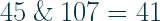
This can be easily proved as follows
   0b00101101   (45 in decimal  - 0x2D in hexadecimal)
&  0b01101011   (107 in decimal - 0x6B in hexadecimal)
-------------
   0b00101001   (41 in decimal  - 0x29 in hexadecimal)
Note that if the logical AND operator (&&) had been used instead of the bitwise AND operator (&) in the previous example, the result would be true, a boolean value represented by the integer value 1.
   0b00101101   (true as it is a non-zero value)
&& 0b01101011   (true as it is a non-zero value)
-------------
         true   (may be represented as 1 in memory)
In C, the integer value 0 is considered false, while any non-zero integer value is considered true. This is important to understand when working with Boolean expressions and control statements in C programming. In the previous example, the result of the logical AND operator (&&) applied to the operands 45 and 107 would be true (i.e. the integer value 1) since both operands are non-zero.
In C programming, the integer value 0 is considered false, while any non-zero integer value is considered true. It’s important to understand this when working with Boolean expressions and control statements in C. For example, if in the previous bitwise AND operator example, we would adopt the Logic AND we would have true, which is represented by the integer value 1 because both operands are non-zero

So the important remark here is that
In C, the bitwise AND operator
&and the logical AND operator&&are two different operators with distinct functions.
Bitwise OR
Once more, let’s quickly recap how the OR operator works.
The OR operator returns 1 if any of its inputs are 1
| A | B | A OR B |
|---|---|---|
| 0 | 0 | 0 |
| 1 | 0 | 1 |
| 0 | 1 | 1 |
| 1 | 1 | 1 |
The bitwise OR operator is a binary operator denoted by the symbol |. It operates on two integer operands and returns a new integer value where each bit is the OR of the corresponding bits in the operands.
If we are to perform a bitwise OR operation with pencil and paper, the two operands are first converted to binary format, and then each corresponding bit in the two binary numbers is compared. If one of the bits is 1, the resulting bit is set to 1. Otherwise, the resulting bit is set to 0.
For example, consider the following bitwise OR operation:
   0b10100101   (165 in decimal - 0xA5 in hexadecimal)
|  0b11001011   (203 in decimal - 0xCB in hexadecimal)
-------------
   0b11101111   (239 in decimal - 0xEF in hexadecimal)
Once more the Logical OR (||) is different from the bitwise OR operator (|). Swapping the operator in the previous example, the result would be true, a boolean value represented by the integer value 1
   0b10100101   (true as it is a non-zero value)
|| 0b11001011   (true as it is a non-zero value)
-------------
         true   (may be represented as 1 in memory)
Once more the important remark is that
In C, the bitwise OR operator
|and the logical OR operator||are two different operators with distinct functions.
Bitwise XOR
Let us recap the XOR also
The XOR operator returns 1 if and only if exactly one of its inputs is 1
| A | B | A XOR B |
|---|---|---|
| 0 | 0 | 0 |
| 1 | 0 | 1 |
| 0 | 1 | 1 |
| 1 | 1 | 0 |
The bitwise XOR operator is a binary operator denoted by the symbol ^. It operates on two integer operands and returns a new integer value where each bit is the XOR of the corresponding bits in the operands.
If we are to perform a bitwise XOR operation with pencil and paper, the two operands are first converted to binary format, and then each corresponding bit in the two binary numbers is compared. If only one of the bits is 1, the resulting bit is set to 1. Otherwise, the resulting bit is set to 0.
For example, consider the following bitwise XOR operation:
   0b10100101   (165 in decimal - 0xA5 in hexadecimal)
^  0b11001011   (203 in decimal - 0xCB in hexadecimal)
-------------
   0b01101110   (110 in decimal - 0x6E in hexadecimal)
In this case, the distinction between the bitwise XOR ^ and the logical XOR ^^ operators is clear, as the previous example will yield a significantly dissimilar result
   0b10100101   (165 in decimal - 0xA5 in hexadecimal)
^^ 0b11001011   (203 in decimal - 0xCB in hexadecimal)
-------------
        false   (represented as 0 in memory)
The reason for this is that, from a logical perspective, both operands are considered true since they are non-zero integers, and the result of true XOR true is false.
The usual remark is that
In C, the bitwise XOR operator
^and the logical XOR operator^^are two different operators with distinct functions.
Bitwise NOT aka One’s Complement
A NOT, differently from the formers, acts on a single input
The NOT operator inverts his input
| A | NOT A |
|---|---|
| 0 | 1 |
| 1 | 0 |
The bitwise NOT operator, often referred to as One’s complement is a binary operator denoted by the symbol ~. It operates on one integer operand and returns a new integer value where each bit is the inverse of the corresponding bits in the operand.
The following is an example of this operator
~  0b11001011   (203 in decimal - 0xCB in hexadecimal)
-------------
   0b00110100   (52 in decimal  - 0x34 in hexadecimal)
Once more, the distinction between the bitwise NOT ~ and the logical NOT ! operators is clear, as the previous example will yield a significantly dissimilar result
!  0b11001011   (203 in decimal - 0xCB in hexadecimal)
-------------
        false   (represented as 0 in memory)
In C, the bitwise NOT operator
~and the logical NOT operator!are two different operators with distinct functions..
Bit shifting
The left shift operator << and the right shift operator >> are used in C to shift the bits of a value left or right by a specified number of positions.
These operators take two operands: the left operand is the value to be shifted and the right operand specifies the number of positions to shift. For example, consider the expression
x = y << 2;
shifts the bits of y to the left of 2 positions and assigns the result to x. If we were to perform a bit shift operation with pencil and paper we would need to convert the left operand into binary and then perform the operation. As an example, the following example shows how to shift 342 on the right of three position
342 >> 3
0b0001 0101 1001 >> 3
0b0000 0010 1011
43
One thing to be taken into account before doing the operation is that the size of the shift register often depends on the architecture and when we shift left or right all the bits overflowing the register will be lost and become 0.
Let us consider that we are working on an 8-bit architecture, in this case
0xFF << 2 = 0xFC
The two most significant bits overflowed the shift register during the operation and are lost. Two empty bits are introduced on the right side. The result would be different on a 16-bit architecture
0xFF << 2 = 0x3FC
As in this case, the two most significant bits are still there. Finally, another thing that could truncate the result of the operation is the type in use for the storing variable in languages with strict types such as C. For example, the following code
#include <stdio.h>
#include <stdint.h>

int main() {

  int myvar = 0XFF;
  uint8_t res = myvar << 2;

  printf("The result is 0x%X\r\n", res);

  return 0;
}
outputs
The result is 0xFC
The reason is that the variable res is an 8-bit variable and the value stored in there gets truncated.
Always pay attention to possible truncations when operating bit shifting
Thank you for the information
Thanks for reading