
Using STM32 I2C with ChibiOS
Important notice
Please note that the information contained in this article may no longer be accurate or useful due to changes in the ChibiOS codebase and ChibiStudio.
Unfortunately, at the moment there is no direct replacement for this article. However, we are in the process of rewriting the series with updated information, a better writing style, and improved ease of use. The new series will also be completed with a larger set of examples and exercises to help you better understand how to use ChibiOS and ChibiStudio.
We welcome any feedback or suggestions you may have, so please don’t hesitate to get in touch with us.
Thank you for your interest in our content.
The Inter-Integrated Circuit
The Inter-Integrated Circuit (often shored as I2C or I2C bus pronounced I-squared-C or alternatively I-two-C) is a widely used synchronous serial communication peripheral which communicates in half duplex mode using a multi-master-multi-slave architecture.
Like the SPI, the I2C is a Synchronous Serial bus, and the clock signal is generated by one of the endpoint and provided to the others through a specific Serial Clock Line often shorted as SCL by a party which is named Master.
In half-duplex buses, the communication happens on the same line no matter the direction. The I2C uses indeed a single data line known as Serial Data often shorted as SDA.
The slave selection happens sending additional data along with information and implementing a protocol: no additional wires are required and I2C is often called two-wire serial in contrast to the four-wire one (the SPI).
I2C highlights
The whole I2C communication happens on the two wire which can be driven by all the bus contenders. To avoid short circuits the I2C uses open drain lines with pull up resistor with typical voltages of 3.3 or 5 V: when bus is in idle condition both SDA and SCL assume an high logic value.
Each I2C transaction begins with a Start condition (SCL high and SDA moves from high to low) and ends with a Stop condition (SCL high and SDA moves from low to high). A transaction is composed by one or more messages where each message is 1 byte word (8-bit) plus an addition bit which has the purpose to guarantee synchronization between master and slave: Acknowledge/Not acknowledge (ACK/NACK) bit.
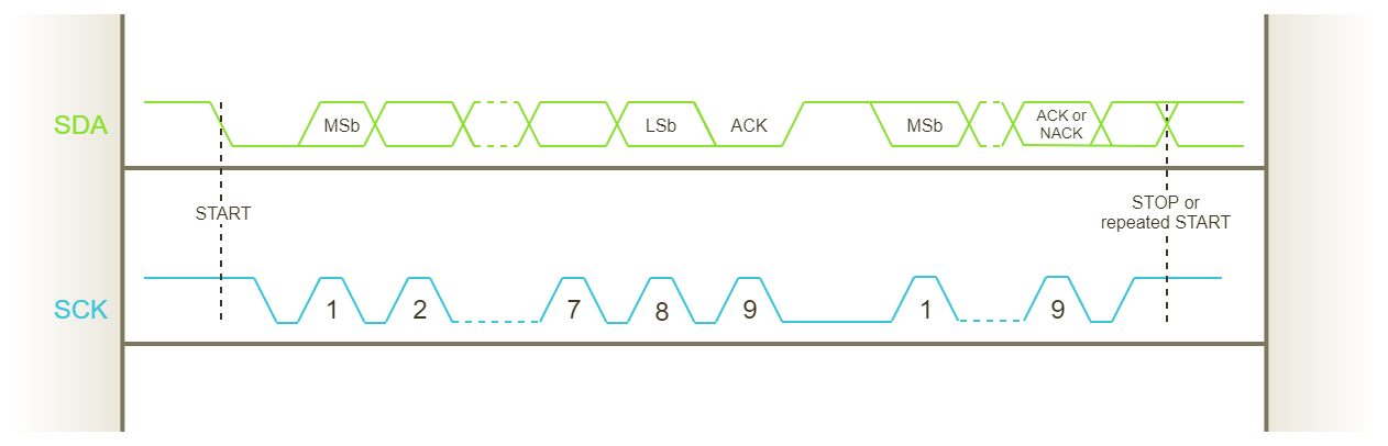
The communication cannot stop in the middle of the transaction: To prematurely abort the operation the receiver as to issue a NACK and after that the master has to issue the Stop Condition otherwise the bus will be in an undefined condition.
The first two word are used to establish the slave to which the communication is addressed, the type of communication and indirectly the number of messages of the transaction. Such addition data is usually know as protocol overhead. The first byte includes the Slave Address (shorted as SAD and having usually 7-bit lenght MSB bun in certain cases also 10-bit) and a read/write bit (R/W 1-bit LSB where read is 1 and write is 0). If slave is a device having registers, the second word is often used to issue which slave sub register the master wants to read/write (often shorted as SUB). At this point in case of read the slave will reply a certain number of messages and the master has to provide clock for each messages, in case of write the master will send a certain number of messages. Communication always ends with a stop condition.
While some of these stuff are well specified by I2C standard others depends on slave thus you should always refer to their user manual. Note that if a device is I2C compliant will most likely be aligned to the I2C specification.
The communication baud rate is adjustable according to some well specified values:
- 10 kbit/s in the Low-speed mode,
- 100 kbit/s in the Standard mode,
- 400 kbit/s in the Fast mode,
- 1 Mbit/s in the Fast mode plus
- 3.4 Mbit/s in the High Speed mode.
Anyway note that these values refers only to clock speed and thus does not take in account protocol overhead as well as clock stretching and other condition which makes the actual baud rate lower than the selected value.
The STM32 I2C
Across the various STM32 subfamilies there are three different hardware version of the I2C cell. We have already explained how to identify the driver version of your STM32 board here reporting them in a table. Anyway, as quick reference:
- STM32F1xx, STM32F2xx, STM32F4xx, and STM32L1xx use I2Cv1;
- STM32F0xx, STM32F3xx, STM32F7xx, STM32L0xx and STM32L4xx use I2Cv2;
- STM32H7xx uses I2Cv3.
The differences between various I2C versions are minimal and basically related to exposed configuration registers. STM32 allows:
- both master and slave mode,
- multi-master mode,
- to configure the baud-rate as Standard mode, Fast mode or Fast mode plus (only I2Cv2 and I2Cv3),
- to address slave in 7-bit or 10-bit mode (only I2Cv2 and I2Cv3),
- to programmable clock stretching and hold/setup time (only I2Cv2 and I2Cv3).
Note that STM32 offers many I2C instances (from 2 in the small packages up to 4 in larger packages). I2C cells are identified with a progressive number (i.e. I2C 1, I2C 2, I2C 3 and so on). Note also that I2C bus relies on GPIO alternate functions to be able to get in touch with the outside world.
The ChibiOS I2C driver
The current ChibiOS I2C driver allows only master mode offering a simple interface to use I2C in synchronous way only.
Each API of the I2C Driver starts with the prefix “i2c”. Function names are camel-case, pre-processor constants uppercase and variables lowercase.
Different driver same approach
Comparing the I2C driver with previously presented SPI Driver or Serial Driver, we can notice that there are some certitudes in ChibiOS: one of these is for sure the consistency of design patterns. The I2C driver is organized like every other simple driver of ChibiOS\HAL:
- The whole driver subsystem can be enabled disabled through the proper switch in the halconf.h. The switch name is HAL_USE_I2C.
- To use the driver we have then to assign it a I2C peripheral acting on mcuconf.h.
- Assigning a peripheral a new object will become available: I2CD1 on I2C 1 assignation, I2CD2 on I2C 2 and so on.
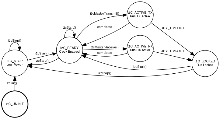
- Each I2CDx object represent a driver which implements a Finite State Machine.
- A driver to be used shall be initialized but this is done automatically on halInit();
- Each driver operation (e.g. a master transmit) can be done only if driver has been properly started. This requires a call to i2cStart().
- The i2cStart() receives as usual two parameters: a pointer to the driver and a pointer to its configuration.
- If the driver is not used it can be stopped through the i2cStop().
The following figure represent the state machine of the driver.
Configuring the I2C
The I2C configuration structure has not some common fields but it depends entirely on hardware. The configuration is completely different between I2Cv1 and I2Cv2/I2Cv3 (which has the same configuration structure).
I2Cv1 configuration structure
The I2Cv1 is extremely simple and has basically three fields:
/**
 * @brief   Type of I2C driver configuration structure.
 */
typedef struct {
  /* End of the mandatory fields.*/
  i2copmode_t     op_mode;       /**< @brief Specifies the I2C mode.        */
  uint32_t        clock_speed;   /**< @brief Specifies the clock frequency.
                                      @note Must be set to a value lower
                                      than 400kHz.                          */
  i2cdutycycle_t  duty_cycle;    /**< @brief Specifies the I2C fast mode
                                      duty cycle.                           */
} I2CConfig;
where op_mode represent the I2C mode which almost always we will configure as OPMODE_I2C and which available values are:
/**
 * @brief   Supported modes for the I2C bus.
 */
typedef enum {
  OPMODE_I2C = 1,
  OPMODE_SMBUS_DEVICE = 2,
  OPMODE_SMBUS_HOST = 3,
} i2copmode_t;
As side note the SMBUS is a lightweight communication bus derivative of I2C usually found in computer motherboards. It is used for communication with the power source transmitting ON/OFF instructions. In 99% cases we have to use complex devices which relies on I2C mode.
The second parameter is clock_speed and is a number representing the baudrate. Many devices communicates in standard mode (100 kbps i.e 100000) or fast mode (400 kbps i.e 400000).
The last parameter specify the clock duty cycle and can be
/**
 * @brief   Supported duty cycle modes for the I2C bus.
 */
typedef enum {
  STD_DUTY_CYCLE = 1,
  FAST_DUTY_CYCLE_2 = 2,
  FAST_DUTY_CYCLE_16_9 = 3,
} i2cdutycycle_t;
In Standard mode we should select STD_DUTY_CYCLE while in Fast mode FAST_DUTY_CYCLE_2.
Thus I2Cv1 configuration is trivial and as example this configuration is one of the most used dealing with MEMS when I am using STM32 Nucleo-64 F401 which is equipped with I2Cv1
static const I2CConfig i2ccfg = {
  OPMODE_I2C,
  400000,
  FAST_DUTY_CYCLE_2,
};
I2Cv2/I2Cv3 configuration structure
The configuration structure of I2Cv2 and I2Cv3 is identical and exposes three registes
/**
 * @brief   Type of I2C driver configuration structure.
 */
typedef struct {
  /**
   * @brief   TIMINGR register initialization.
   * @note    Refer to the STM32 reference manual, the values are affected
   *          by the system clock settings in mcuconf.h.
   */
  uint32_t        timingr;
  /**
   * @brief   CR1 register initialization.
   * @note    Leave to zero unless you know what you are doing.
   */
  uint32_t        cr1;
  /**
   * @brief   CR2 register initialization.
   * @note    Only the ADD10 bit can eventually be specified here.
   */
  uint32_t        cr2;
} I2CConfig;
The first parameter is timingr which represent the value of the I2C Timing Register. It allows to apply some fine tuning to the clock speed, hold and setup time. Bit fields are described in manual and it offers also a series of formula to compute the high and low period as well as rising and falling time.
The second and third parameters cr1 and cr2 are the value of I2C Control Register 1 and I2C Control Register 2 which allows to configure some stuff but which are already internally addressed thus more often are left to 0
These register offer a lot of flexibility but are very difficult to be configured especially the first one. My suggestion is to refer to testhal demo for STM32 equipped with I2Cv2 (e.g STM32F3) to copy a working configuration an adopt it in your project: this would work almost always.
static const I2CConfig i2ccfg = {
  STM32_TIMINGR_PRESC(15U) |
  STM32_TIMINGR_SCLDEL(4U) | STM32_TIMINGR_SDADEL(2U) |
  STM32_TIMINGR_SCLH(15U)  | STM32_TIMINGR_SCLL(21U),
  0,
  0
};
Communication API
As said the I2C communication from the master point of view can be synthesized in these steps:
- The master send the first word with slave address and R/W bit
- The master send the second word with the SUB he wants to read/write
- The master send/receives n words.
This activity can be simply addressed with a single API
/**
 * @brief   Sends data via the I2C bus.
 * @details Function designed to realize "read-through-write" transfer
 *          paradigm. If you want transmit data without any further read,
 *          than set @b rxbytes field to 0.
 *
 * @param[in] i2cp      pointer to the @p I2CDriver object
 * @param[in] addr      slave device address (7 bits) without R/W bit
 * @param[in] txbuf     pointer to transmit buffer
 * @param[in] txbytes   number of bytes to be transmitted
 * @param[out] rxbuf    pointer to receive buffer
 * @param[in] rxbytes   number of bytes to be received, set it to 0 if
 *                      you want transmit only
 * @param[in] timeout   the number of ticks before the operation timeouts,
 *                      the following special values are allowed:
 *                      - @a TIME_INFINITE no timeout.
 *                      .
 *
 * @return              The operation status.
 * @retval MSG_OK       if the function succeeded.
 * @retval MSG_RESET    if one or more I2C errors occurred, the errors can
 *                      be retrieved using @p i2cGetErrors().
 * @retval MSG_TIMEOUT  if a timeout occurred before operation end.
 *
 * @api
 */
msg_t i2cMasterTransmitTimeout(I2CDriver *i2cp,
                               i2caddr_t addr,
                               const uint8_t *txbuf,
                               size_t txbytes,
                               uint8_t *rxbuf,
                               size_t rxbytes,
                               sysinterval_t timeout) {
  ...
}
This API receives 7 parameters:
- the pointer to the I2C driver which shall be already started
- the SAD having 7-bit lenght non shifted (without the R/W)
- a pointer to a transmission buffer (can be NULL)
- the number of word to transmit (can be 0)
- a pointer to a reception buffer (can be NULL)
- the number of word to receive (can be 0)
- an operation timeout expressed as interval useful to avoid stuck in this fuction
If we want to write only we can set rxbuf to NULL and rxbytes to 0. Similarly some slave devices have has not registers and can be read only. In this case after issuing the slave address and the read bit (first word) it will start to reply with words until the master does not issue the stop condition: in such case we could set txbuf to NULL and txbytes to 0, or alternatively use the function
/**
 * @brief   Receives data from the I2C bus.
 *
 * @param[in] i2cp      pointer to the @p I2CDriver object
 * @param[in] addr      slave device address (7 bits) without R/W bit
 * @param[out] rxbuf    pointer to receive buffer
 * @param[in] rxbytes   number of bytes to be received
 * @param[in] timeout   the number of ticks before the operation timeouts,
 *                      the following special values are allowed:
 *                      - @a TIME_INFINITE no timeout.
 *                      .
 *
 * @return              The operation status.
 * @retval MSG_OK       if the function succeeded.
 * @retval MSG_RESET    if one or more I2C errors occurred, the errors can
 *                      be retrieved using @p i2cGetErrors().
 * @retval MSG_TIMEOUT  if a timeout occurred before operation end.
 *
 * @api
 */
msg_t i2cMasterReceiveTimeout(I2CDriver *i2cp,
                              i2caddr_t addr,
                              uint8_t *rxbuf,
                              size_t rxbytes,
                              sysinterval_t timeout) {
  ...
}
Timeout can be disabled choosing TIME_INFINITE or using the macros
/**
 * @brief   Wrap i2cMasterTransmitTimeout function with TIME_INFINITE timeout.
 * @api
 */
#define i2cMasterTransmit(i2cp, addr, txbuf, txbytes, rxbuf, rxbytes)       \
  (i2cMasterTransmitTimeout(i2cp, addr, txbuf, txbytes, rxbuf, rxbytes,     \
                            TIME_INFINITE))

/**
 * @brief   Wrap i2cMasterReceiveTimeout function with TIME_INFINITE timeout.
 * @api
 */
#define i2cMasterReceive(i2cp, addr, rxbuf, rxbytes)                        \
  (i2cMasterReceiveTimeout(i2cp, addr, rxbuf, rxbytes, TIME_INFINITE))
which actually are re-definitions of the previous presented functions with TIME_INFINITE timeout.
To conclude, note that these functions return a message which relies on ACK/NACK. This is interesting because in case of communication error software can take an action based on the error flag.
/**
 * @brief   Returns the errors mask associated to the previous operation.
 *
 * @param[in] i2cp      pointer to the @p I2CDriver object
 * @return              The errors mask.
 *
 * @api
 */
i2cflags_t i2cGetErrors(I2CDriver *i2cp) {
  ...
}
where available error flags are
/**
 * @name    I2C bus error conditions
 * @{
 */
#define I2C_NO_ERROR               0x00    /**< @brief No error.            */
#define I2C_BUS_ERROR              0x01    /**< @brief Bus Error.           */
#define I2C_ARBITRATION_LOST       0x02    /**< @brief Arbitration Lost.    */
#define I2C_ACK_FAILURE            0x04    /**< @brief Acknowledge Failure. */
#define I2C_OVERRUN                0x08    /**< @brief Overrun/Underrun.    */
#define I2C_PEC_ERROR              0x10    /**< @brief PEC Error in
                                                reception.                  */
#define I2C_TIMEOUT                0x20    /**< @brief Hardware timeout.    */
#define I2C_SMB_ALERT              0x40    /**< @brief SMBus Alert.         */
/** @} */
Mutual exclusion
The driver offers also a couple of API to acquire and release the bus: i2cAcquireBus and i2cReleaseBus.
/**
 * @brief   Gains exclusive access to the I2C bus.
 * @details This function tries to gain ownership to the I2C bus, if the bus
 *          is already being used then the invoking thread is queued.
 * @pre     In order to use this function the option @p I2C_USE_MUTUAL_EXCLUSION
 *          must be enabled.
 *
 * @param[in] i2cp      pointer to the @p I2CDriver object
 *
 * @api
 */
void i2cAcquireBus(I2CDriver *i2cp) {
  ...
}

/**
 * @brief   Releases exclusive access to the I2C bus.
 * @pre     In order to use this function the option @p I2C_USE_MUTUAL_EXCLUSION
 *          must be enabled.
 *
 * @param[in] i2cp      pointer to the @p I2CDriver object
 *
 * @api
 */
void i2cReleaseBus(I2CDriver *i2cp) {
  ...
}
Such functions are useful when the same I2C driver is used from two threads because they guarantee that none will use that I2C driver until it is acquired avoiding misbehaviour due to concurrent access. Note that these API requires I2C_USE_MUTUAL_EXCLUSION is set to TRUE in the halconf.h file.
Further readings and Hands-on
We have already planned a collection of example and exercises for the I2C driver. If you are interested in follow us on Facebook to be updated on our articles. Anyway, at this moment you could refer to the I2C demo under testhal to give it a try.
Another interesting use of I2C is the HD44780 LDC with backpack:
You can also try the demo under testex for STM32 Nucleo with external x-Nucleo IKS01A1 or IKS01A2 which are expansion board equipped with MEMS which communicates over I2C.
Even STM32F3 Discovery which uses I2C to communicate with LSM303DLHC: this is a 3-axis accelerometer + 3-axis magnetometer connected to the MCU through the I2C. Basically the chip acts like two separate slaves having different registers and different Slave Address.
Previous and next
This article is part of a series of articles which are meant to be tutorials. I have composed them to be read in sequence. Here the previous and next article of this series:
Do you have an example of using this you could link to? I’m trying to figure out what other setup I need to do to use i2c.
Hi tyler,
not yet but there are many examples under testhal and testex.
Thank you so much to do all the work! I also want to learn something about the Can driver. Really hope I can find an article about that here.
Thank you so much! This series of articles are very useful. I also think, it would be great to read about CAN driver. So if you would continue this series, please consider it.
Hello.
Is there a article,for implementation ‘Firmware bypass using 2 i2c ports’ ?
I just think using interrupt, but have no idea.
Help please.
Hi,
I am not sure to understand what ‘Firmware bypass using 2 i2c ports’ means.
It means chibiOS’s I2C master, slave setting.
System configuration :
[Main Chip] ←(1)→ [STM32F4/Chibios/I2CD1]
(1) Main Chip : I2CD1 Master mode
STM32F4 : I2CD1 Slave mode
[STM32F4/Chibios/I2CD2] ←(2)→ [sensor]
(2) STM32F4: I2CD2 Master mode
sensor : I2CD2 Slave mode
Main chip transmits register address(including set value).
STM32F4 receives the address and transmits it to sensor.
STM32F4 receives(=read) sensor value from sensor’s specific address and transmit the value to Main Chip.
Finally, Main chip receives(read) the value and use it.
I said ‘Firmware bypass using 2 i2c ports’ about above.
‘(2)’ is not difficulty.
‘i2cMasterTransmitTimeout’, ‘i2cMasterReceiveTimeout’ functions are implemented, already.
‘(1)’ is main problem to me.
In this case, how can I implement I2C Slave mode on ChibiOS?
I am not sure ChibiOS I2C driver supports the slave mode. You should ask the ChibiOS Forum for that.
Hello, we have, GPIO, ADC, USART, I2C, SPI, it would be nice to have instructions on how to use the USB (Host, HID/MSC) port (there are few instructions on the internet).
I’m building a Data Logger (GitHub Datalogger_2039) with STM32CubeIDE, and to improve performance, I’m trying to learn how to use RTOS, unfortunately I haven’t been able to get the STM32CubeIDE RTOS working yet. So I went back to trying to understand this ChibiOS, which seems to have improved a lot.
I would like to ask if it would be possible to provide a pre-configured image with ChibiOS pre-installed in a virtual machine with a lightweight system, perhaps a Linux Lubuntu, in this way users would have to download only one file and would already be able to make use of the tool.
Hello RH,
if you browse ChibiOS forum you may find an example about USB/HID. USB is all about descriptors and I never had enough time to go into those details.
About the image, I remember Giovanni prepared something like this. Again, look into forum.chibios.org, there was a post about this.
Rocco, I believe that STM32L0xx uses I2Cv2
Yeah jacabetas,
you are right. Thanks for reporting this. I updated the article even if I plan to make something completely new out of it in the near future.