
PWM in hardware with STM32 Timer and ChibiOS
Important notice
Please note that the information contained in this article may no longer be accurate or useful due to changes in the ChibiOS codebase and ChibiStudio.
Unfortunately, at the moment there is no direct replacement for this article. However, we are in the process of rewriting the series with updated information, a better writing style, and improved ease of use. The new series will also be completed with a larger set of examples and exercises to help you better understand how to use ChibiOS and ChibiStudio.
We welcome any feedback or suggestions you may have, so please don’t hesitate to get in touch with us.
Thank you for your interest in our content.
The Pulse Width Modulation
The Pulse Width Modulation (also known as PWM) is a digital modulation technique which uses duty-cycle of square waves to encode information. In communication field PWM surrendered to more advanced communication technique which uses more complex waveforms showing better noise rejection ratio and less transmission errors at highest data rate. Nevertheless, PWM is still used in infrared communication where data rate is very low but transmitter and receiver are cheap.
Anyway low rate communication is not the most relevant use case of PWM which is widely used in many fields very far from communication: maybe the most know use case is the control of Switching Mode Power Supply especially when used to drive inductive load like motors. Another interesting use case for PWM is light dimming especially with LEDs.
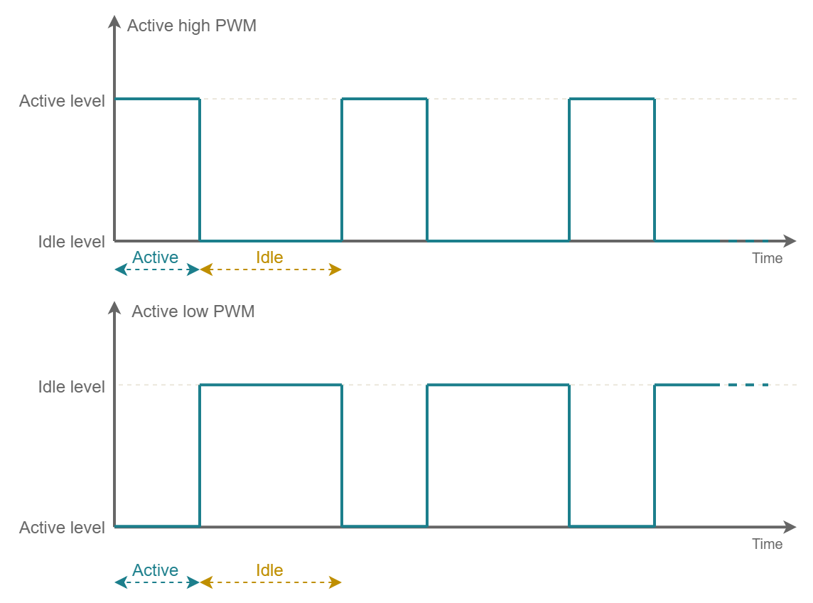
The PWM is a waveform which can basically switch between two states with a negligible raise/fall time and a constant period. The two states are usually two different voltage levels Vhigh and Vlow. In a general sense the two possible states can be named active and idle.
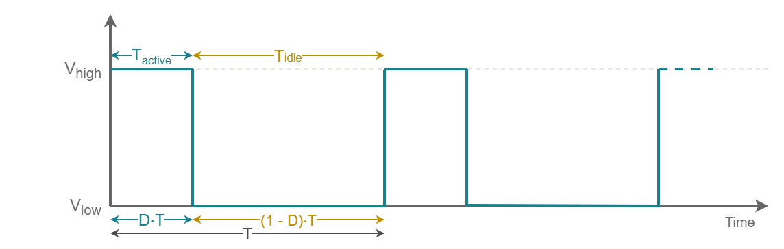
The Period can be thus defined as

The Duty Cycle is a ratio often expressed as percentage which can be defined as

It is not guaranteed that the active state would be Vhigh and idle Vlow (as example if we are using the PWM to switch a P-channel mosfet). Thus we can have two different types of PWM: the Active High (high is active, low is idle) and the Active Low (low is active, high is idle).
The most exploited property of the PWM signal is definitely the proportionality between Duty Cycle and signal mean value. Let us consideran active high PWM like that shown in figure 2. In this case the signal mean value for a periodic signal is defined as
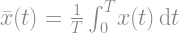
This integral can be split and solved easily


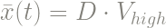
In the particular case were low state is the reference ground the mean value becomes
The STM32 Timer
STM32 Timer (also abbreviated as TIM) is a peripheral which allows to generate PWM signals in hardware and this means once the Timer have been configured and started it can generate a PWM waveform on a certain output PIN without the intervention of the software. Actually the general purpose timer of the STM32 is a peripheral which can be used for a large variety of purposes. Mainly it can be used as reliable timing source, as example to properly schedule tasks in a RTOS like ChibiOS, or to trigger with a precise cadency the ADC peripheral. As said it can be additionally used to generate PWM signals or conversely capture square waves measuring elapsed time between two waveform edges and thus period and duty cycle.
Each STM32 is equipped with a large amount of timers which are identified by a progressive number (TIM1, TIM2, TIM3, and so on). All the timers are independent and they do not share any resources even if they can be synchronised together.
Some timer are known as Advanced Timers as they have some advanced features like the complementary outputs, programmable dead-time and break input to put the timer output in reset or known state. Such features are thought to fulfill Full Bridge control application needs. Usually those timers are the TIM1 and TIM8 but it is not guarantee they are always available on every STM32.
The hardware itself is very complex and offers so many working mode that explain all of them in detail would be difficult and dispersive. Anyway I would like to give you some information about this peripheral and then focus on PWM output mode.
The time base unit
A timer basically is fed with a clock signal and it counts the clock pulses. As the clock speed is know, this basically allows to measure time windows.
On STM32 each Timer has in independent counter which can be configured to count upward or downward: basically the counter increases/decreases its value on each clock pulse and the current value can be read accessing the register TIMx Counter (TIMx_CNT). The timer counter register has a 16-bit depth except on a limited number of timers which are equipped with a 32-bit counter register. Those timer, if available, are usually the TIM2 and TIM5.
A larger counter bit-depth guarantees higher resolution at given full scale. To understand what this means lets take a look to some definitions. The timer resolution is the minimum amount of time the timer is able to count. In term of time magnitude, it is equal to clock period

The timer full scale is the maximum amount of time that can be counted. It depends on timer resolution and counter depth

About clock speed we should take a step back and take a look to clock distribution. On STM32 but more in general on ARM Cortex-M architecture, peripherals are interfaced to memory, core and DMA through the Advanced Peripheral Bus (also shortened as APB). The architecture of this bus is based on the ARM Advanced Microcontroller Bus Architecture (AMBA) which is an open-standard for the connection and management of subsystem in a system-on-chip. Depending on the amount of peripherals and chip size, there could be more than a APB on each micro and usually they are identified by a progressive number (APB1, APB2, APB3 and so on). The main purposes of an APB is to provide clock distribution from the main domain (that of the core, memory and DMA) to the peripheral, as well as provide a memory-mapped register interface. As in STM32 there are dozen of timer, often they are connected on different APB and the maximum clock speed of a timer depends on which APB they are. Even more each APB has is own prescaler to run at a clock speed which is lower or equal to that from the main domain.
Usually on STM32 at least an APB is able to run at the same speed of the ARM Cortex-M core thus at the maximum speed of the whole system. Anyway, to run at maximum speed is not always suitable for all the scenarios. Looking back to previous formula let us consider the case of a STM32F401RE and its TIM9 which is equipped with a 16-bit counter and is connected to APB2 and can be configured to run at 84MHz. At this speed we have an high time resolution which is approximately 11.9 ns but a small full scale in the order of 780 ms.
If we cannot make use of a 32-bit timer the best way to deal with larger time windows would be to reduce clock speed. Even if APB offer a clock prescaler, changing this divider would impact all the peripherals connected to it. To ensure flexibility, each timer is equipped with an independent 16-bit prescaler which can be configured accessing the register TIMx prescaler (TIMx_PSC).
When a timer is running and overflows its maximum value, it rolls over to zero and continues to run. On overflow event the timer launches an interrupt request. Acting on a register known as Timer Auto-Reload Register (TIMx_ARR) is possible to reduce the upper limit and anticipate the rollover. This is actually true only in upperward counting mode when the counter runs from 0 to the value of the TIMx_ARR register then rolls over to 0. In downward counting mode the condition is inverted: the counter runs from the TIMx_ARR value down to 0, generates an interrupt on the underflow event and the rolls over to the TIMx_ARR value continuing to run.
Basically once started the counter continues to run and launch interrupts with a specific frequency. Such kind of interrupt is periodic and we will refer to it as Timer Periodic Interrupt. The frequency of periodic interrupts (at given clock speed) can be changed acting on the Prescaler Register and on the Auto Reload Register value according to the formula

The TIMx_CNT and TIMx_PSC joint with the TIMx_ARR compose the core of the timer which is called Time Base Unit.
The channels
Each STM32 timer is equipped with some repeated sub structures known as Channels. A timer can have up to 4 independent channels which are identified with a progressive number (TIMx_CH1, TIMx_CH2, and so on) and each channel is equipped with additional registers and an I/O line.
The Channel is able to launch additional interrupt when the counter reaches an intermediate value before the overflow/underflow event. This can be done comparing the current counter value with that preloaded in an additional channel register known as Capture/Compare Register (TIMx_CCR1, TIMx_CCR2, etc.). Obviously such value shall be smaller than that stored in the TIMx_ARR. Such kind of interrupts are channel dependent so we will refer to them as Timer Channel Interrupts.
The operation mode of a channel can be changed acting on the Capture/Compare Mode Register (TIMx_CCMR1, TIMx_CCMR2, etc.). When a channel is configured in PWM mode it is able to change the logic level of its I/O line on periodic and channel interrupts. Just remember, to use this feature, we need to reroute some GPIO connections assigning them to TIM (take a look to GPIO article if you are not familiar with).
The PWM mode
When a Channel is configured in PWM mode the timer can generate a squarewave toggling its I\O line twice per period.
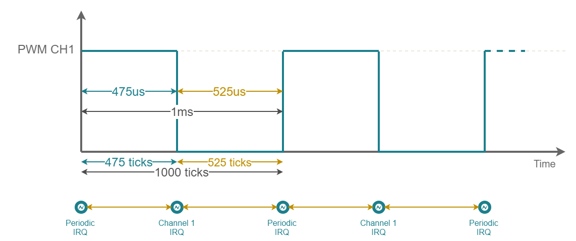
To clarify how PWM mode works let us do a simple example. Let us assume we would like to generate a PWM with a period of 1 kHz and duty cycle 47.5% active high. To do that let configure the timer to run at a frequency of 1MHz. We can then configure the TIMx_ARR to 1000 having a periodic interrupt every millisecond (which is equal to our PWM frequency e.g. 1 kHz) and the TIMx_CCR1 to 475 (where the ratio TIMx_CCR1/TIMx_ARR is equal to our PWM duty cycle).
We can also use the same timer to generate another PWM signal having the same period but a different duty cycle. As example configuring the TIMx_CCR2 to 700 we would have
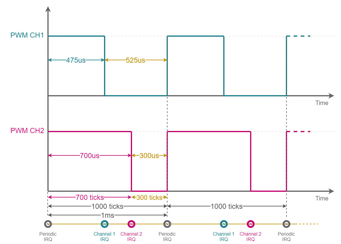
Thus basically with a 4 channel timer we can generate up to 4 PWM signals which have the same period and arbitrary duty cycle.
As each channel has independent Capture\Compare module and shared Auto Reload Register using a timer it possible to generate a PWM signal for each channel having same period but different duty cycle.
Note that when PWM is configured as active high the timer will switch high the channel line on periodic interrupt and low on channel interrupt. On contrary when it is configured in PWM mode active low the timer will set low on periodic and high on channel.
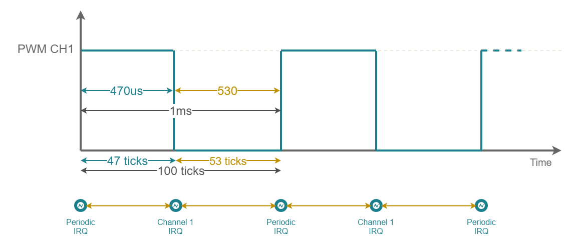
What if we reduce the timer speed from 1MHz to 100kHz? Well we could scale all the previous value by 10 but we would lose resolution on duty cycle. In such case indeed the minimum duty we can set is 1%. Back to the previous example, with these settings, we can set duty cycle to 47% or 48% but not to 47.5%.
More in general the duty resolution is given by the formula

Note that on STM32 usually TIM6 and TIM7 have no channel as they are deputy to act as timing source for internal ADC and DAC.
The ChibiOS PWM Driver
The ChibiOS PWM driver exploits the PWM output mode capability of STM32 TIM to generate PWM signal in hardware offering also the chance to intercept periodic and channel interrupts through callbacks. This allows to generate PWM on arbitrary I/O line not necessarily internally connected to a timer channel with software intervention.
Each API of the PWM Driver starts with the prefix “pwm”. Function names are camel-case, pre-processor constants uppercase and variables lowercase.
Differently from other peripherals Timer is the same across all the STM32 subfamilies. Thus we have only TIMv1.
Different driver same approach
We have presented many driver in this article series and again in PWM driver we can notice same certitudes we got used to dealing with ChibiOS. The design patterns are constant and the PWM driver is organized like every other simple driver of ChibiOS\HAL:
- The whole driver subsystem can be enabled disabled through the proper switch in the halconf.h. The switch name is HAL_USE_PWM.
- To use the driver we have then to assign a TIM peripheral to it acting on mcuconf.h.
- Assigning a peripheral to the driver a new object will become available: PWMD1 on TIM1 assignation, PWMD2 on TIM2 and so on.
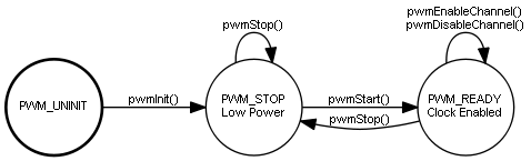
- Each PWMDx object represent a driver which implements a Finite State Machine.
- A driver to be used shall be initialized but this is done automatically on halInit();
- The driver shall be properly configured before to be used. This requires a call to pwmStart().
- The pwmStart() receives as usual two parameters: a pointer to the driver and a pointer to its configuration.
- If the driver is not used it can be stopped through the pwmStop().
The following figure represent the state machine of the driver.
Managing peripheral assignation related conflicts
The TIM peripheral can be assigned to many driver like ICU, GPT and ST. Before to assign a timer to the PWM driver, user should take care to check whereas it is already assigned to another driver.
A special care is required by ST which stands for System Tick: the ChibiOS scheduler relies on hardware timer to achieve reliable timing for scheduling purposes. Thus, when available, it uses a 32-bit timer to have a larger resolution independently from clock tree configuration.
A timer is assinged to the ST in the mcuconf.h header through the define STM32_ST_USE_TIMER. The following code as grabbed from the default demo for STM32 Nucleo-64 F401RE and here the ST uses the TIM2. This means basically PWMD2 cannot be used.
/*
 * ST driver system settings.
 */
#define STM32_ST_IRQ_PRIORITY               8
#define STM32_ST_USE_TIMER                  2
To assign TIM2 to the PWM we have to deassign it from ST. By default ST expects a 32-bit resolution timer, and the only alternative is the TIM5. Anyway, if we accept to lose resolution we can also reduce the ST resolution acting on chconf.h and moving CH_CFG_ST_RESOLUTION from 32 to 16
/**
 * @brief   System time counter resolution.
 * @note    Allowed values are 16 or 32 bits.
 */
#if !defined(CH_CFG_ST_RESOLUTION)
#define CH_CFG_ST_RESOLUTION                32
#endif
Configuring the PWM
The PWM Driver offers a rich configuration structure which allow to properly configure the STM32 timer to work in PWM mode. These fields are aligned to what we have seen in the previous chapter.
/**
 * @brief   Type of a PWM driver configuration structure.
 */
typedef struct {
  /**
   * @brief   Timer clock in Hz.
   * @note    The low level can use assertions in order to catch invalid
   *          frequency specifications.
   */
  uint32_t                  frequency;
  /**
   * @brief   PWM period in ticks.
   * @note    The low level can use assertions in order to catch invalid
   *          period specifications.
   */
  pwmcnt_t                  period;
  /**
   * @brief Periodic callback pointer.
   * @note  This callback is invoked on PWM counter reset. If set to
   *        @p NULL then the callback is disabled.
   */
  pwmcallback_t             callback;
  /**
   * @brief Channels configurations.
   */
  PWMChannelConfig          channels[PWM_CHANNELS];
  /* End of the mandatory fields.*/
  /**
   * @brief TIM CR2 register initialization data.
   * @note  The value of this field should normally be equal to zero.
   */
  uint32_t                  cr2;
#if STM32_PWM_USE_ADVANCED || defined(__DOXYGEN__)
  /**
   * @brief TIM BDTR (break & dead-time) register initialization data.
   * @note  The value of this field should normally be equal to zero.
   */                                                                     \
   uint32_t                 bdtr;
#endif
   /**
    * @brief TIM DIER register initialization data.
    * @note  The value of this field should normally be equal to zero.
    * @note  Only the DMA-related bits can be specified in this field.
    */
   uint32_t                 dier;
} PWMConfig;
The first parameter is frequency and represent the timer clock speed. In simple words this parameter will be used to compute the prescaler value starting from the APB frequency. Note that while the APB represent an upper limit to the reachable frequency, the timer counter depth provides an lower limit to it.

ChibiOS allows to catch invalid frequency specification through the assertions. This debugging mechanism can be enabled in chconf.h and, in case, triggers an error at compile time when the choosen frequency is invalid.
/**
 * @brief   Debug option, consistency checks.
 * @details If enabled then all the assertions in the kernel code are
 *          activated. This includes consistency checks inside the kernel,
 *          runtime anomalies and port-defined checks.
 *
 * @note    The default is @p FALSE.
 */
#if !defined(CH_DBG_ENABLE_ASSERTS)
#define CH_DBG_ENABLE_ASSERTS               FALSE
#endif
Assertions, like other debugging mechanism, should always be enabled during the development phase and disabled when the application is ready to be deployed.
The second parameter is period and represent the initial PWM period expressed as clock pulses. Once that timer and PWM frequency are know, this value can easily be computed using the formula

period is limited by TIMx_ARR bit depth and invalid value can be catched using assertion as well.
The third parameter callback is a pointer to a callable which the driver will call on periodic interrupt. It can be set to NULL if unused.
The fourth parameter is an array of structures having the same size of the available channels. This size of course depends on specific timer and each element represents the configuration of that channel
/**
 * @brief   Type of a PWM driver channel configuration structure.
 */
typedef struct {
  /**
   * @brief Channel active logic level.
   */
  pwmmode_t                 mode;
  /**
   * @brief Channel callback pointer.
   * @note  This callback is invoked on the channel compare event. If set to
   *        @p NULL then the callback is disabled.
   */
  pwmcallback_t             callback;
  /* End of the mandatory fields.*/
} PWMChannelConfig;
The first element of the structure is the channel mode, while the second element is again a callback which will be called on channel interrupt. The following code represent the available channel modes.
/**
 * @brief   Output not driven, callback only.
 */
#define PWM_OUTPUT_DISABLED                     0x00U

/**
 * @brief   Positive PWM logic, active is logic level one.
 */
#define PWM_OUTPUT_ACTIVE_HIGH                  0x01U

/**
 * @brief   Inverse PWM logic, active is logic level zero.
 */
#define PWM_OUTPUT_ACTIVE_LOW                   0x02U
In addition to these parameters the driver accept also 3 additional fields which represent three registers of the timer: the Control Register 2 (TIMx_CR2), the Break and Dead Time Register (TIMx_BDTR) and the DMA/interrupt enable register (TIMx_DIER). In standard application their value can be left to 0 but note that the TIMx_BDTR is available only in Advanced Timers: because of that its field can be activated optionally setting the STM32_PWM_USE_ADVANCED preprocessor switch to TRUE mcuconf.h.
The following snippet of code is an example of PWM configuration and related callback
static PWMConfig pwmcfg = {
  10000,                                    /* 10kHz PWM clock frequency.     */
  10000,                                    /* Initial PWM period 1S.         */
  NULL,                                     /* Period callback.               */
  {
   {PWM_OUTPUT_ACTIVE_HIGH, NULL},          /* CH1 mode and callback.         */
   {PWM_OUTPUT_DISABLED, NULL},             /* CH2 mode and callback.         */
   {PWM_OUTPUT_DISABLED, NULL},             /* CH3 mode and callback.         */
   {PWM_OUTPUT_DISABLED, NULL}              /* CH4 mode and callback.         */
  },
  0,                                        /* Control Register 2.            */
  0                                         /* DMA/Interrupt Enable Register. */
};
This configuration sets the timer clock to 10 kHz, the PWM initial period to 1S, enables only the Channel 1. The PWM configuration is used on pwmStart specifying which PWM Driver we are actually going to use.
/**
 * @brief   Configures and activates the PWM peripheral.
 * @note    Starting a driver that is already in the @p PWM_READY state
 *          disables all the active channels.
 *
 * @param[in] pwmp      pointer to a @p PWMDriver object
 * @param[in] config    pointer to a @p PWMConfig object
 *
 * @api
 */
void pwmStart(PWMDriver *pwmp, const PWMConfig *config) {
  ...
}
As instance the following code is using the configuration to setup the PWM Driver 1 which relies on TIM1.
pwmStart(&PWMD1, &pwmcfg);
PWM driver configuration can be changed on the fly restarting the driver with a new configuration.
Enabling/Disabling PWM channels
The configuration structure does not specifies any information about the duty cycle. Indeed the pwmStart configures the timer but does not output anything. To see something on the I/O line we have to enable the channel. Beside of that, remember that the related I/O line shall be properly configured as Alternate Function.
A PWM channel can be enabled using the a specific API
/**
 * @brief   Enables a PWM channel.
 * @pre     The PWM unit must have been activated using @p pwmStart().
 * @post    The channel is active using the specified configuration.
 * @note    Depending on the hardware implementation this function has
 *          effect starting on the next cycle (recommended implementation)
 *          or immediately (fallback implementation).
 *
 * @param[in] pwmp      pointer to a @p PWMDriver object
 * @param[in] channel   PWM channel identifier (0...channels-1)
 * @param[in] width     PWM pulse width as clock pulses number
 *
 * @api
 */
void pwmEnableChannel(PWMDriver *pwmp,
                      pwmchannel_t channel,
                      pwmcnt_t width) {

  ...
}
This API receives a pointer to the PWM driver, a channel identifier and the pulse width expressed as clock pulses. The channel identifier is a progressive number starting from 0 to N-1 whereas N is the number of available channels on that timer.
The driver offers some helper to compute the width starting from a fraction
/**
 * @brief   Converts from fraction to pulse width.
 * @note    Be careful with rounding errors, this is integer math not magic.
 *          You can specify tenths of thousandth but make sure you have the
 *          proper hardware resolution by carefully choosing the clock source
 *          and prescaler settings, see @p PWM_COMPUTE_PSC.
 *
 * @param[in] pwmp      pointer to a @p PWMDriver object
 * @param[in] denominator denominator of the fraction
 * @param[in] numerator numerator of the fraction
 * @return              The pulse width to be passed to @p pwmEnableChannel().
 *
 * @api
 */
#define PWM_FRACTION_TO_WIDTH(pwmp, denominator, numerator)                 \
  ((pwmcnt_t)((((pwmcnt_t)(pwmp)->period) *                                 \
               (pwmcnt_t)(numerator)) / (pwmcnt_t)(denominator)))
an angle
/**
 * @brief   Converts from degrees to pulse width.
 * @note    Be careful with rounding errors, this is integer math not magic.
 *          You can specify hundredths of degrees but make sure you have the
 *          proper hardware resolution by carefully choosing the clock source
 *          and prescaler settings, see @p PWM_COMPUTE_PSC.
 *
 * @param[in] pwmp      pointer to a @p PWMDriver object
 * @param[in] degrees   degrees as an integer between 0 and 36000
 * @return              The pulse width to be passed to @p pwmEnableChannel().
 *
 * @api
 */
#define PWM_DEGREES_TO_WIDTH(pwmp, degrees)                                 \
  PWM_FRACTION_TO_WIDTH(pwmp, 36000, degrees)
or a percentage
/**
 * @brief   Converts from percentage to pulse width.
 * @note    Be careful with rounding errors, this is integer math not magic.
 *          You can specify tenths of thousandth but make sure you have the
 *          proper hardware resolution by carefully choosing the clock source
 *          and prescaler settings, see @p PWM_COMPUTE_PSC.
 *
 * @param[in] pwmp      pointer to a @p PWMDriver object
 * @param[in] percentage percentage as an integer between 0 and 10000
 * @return              The pulse width to be passed to @p pwmEnableChannel().
 *
 * @api
 */
#define PWM_PERCENTAGE_TO_WIDTH(pwmp, percentage)                           \
  PWM_FRACTION_TO_WIDTH(pwmp, 10000, percentage)
This last is very interesting as we usually express the duty in form of percentage. As example the next snippet enables the TIM1_CH1 with a duty of 47.5%
pwmEnableChannel(&PWMD1, 0, PWM_PERCENTAGE_TO_WIDTH(&PWMD1, 4750))
It is possible to change the channel duty cycle on the fly calling the pwmEnableChannel repeatedly but with a different width.
To disable a channel there is another function named pwmDisableChannel. Such function receives only the PWM Driver and the channel identifier.
/**
 * @brief   Disables a PWM channel and its notification.
 * @pre     The PWM unit must have been activated using @p pwmStart().
 * @post    The channel is disabled and its output line returned to the
 *          idle state.
 * @note    Depending on the hardware implementation this function has
 *          effect starting on the next cycle (recommended implementation)
 *          or immediately (fallback implementation).
 *
 * @param[in] pwmp      pointer to a @p PWMDriver object
 * @param[in] channel   PWM channel identifier (0...channels-1)
 *
 * @api
 */
void pwmDisableChannel(PWMDriver *pwmp, pwmchannel_t channel) {
  ...
}
Changing period on the fly
The PWM period can be changed on the fly with another API which overwrites the configuration applied on pwmStart.
/**
 * @brief   Changes the period the PWM peripheral.
 * @details This function changes the period of a PWM unit that has already
 *          been activated using @p pwmStart().
 * @pre     The PWM unit must have been activated using @p pwmStart().
 * @post    The PWM unit period is changed to the new value.
 * @note    If a period is specified that is shorter than the pulse width
 *          programmed in one of the channels then the behavior is not
 *          guaranteed.
 *
 * @param[in] pwmp      pointer to a @p PWMDriver object
 * @param[in] period    new cycle time in ticks
 *
 * @api
 */
void pwmChangePeriod(PWMDriver *pwmp, pwmcnt_t period) {

  ...
}
Callbacks and notifications
The PWM driver can trigger a callback on periodic interrupt and a callback on channel interrupt. Such kind of callbacks can be setup acting on PWM configuration. As instance the following code is identical to the previous example with the difference that here we have setup a periodic and a channel callback.
static void pwmpcb(PWMDriver *pwmp) {

  (void)pwmp;
  palClearPad(GPIOA, GPIOA_LED_GREEN);
}

static void pwmc1cb(PWMDriver *pwmp) {

  (void)pwmp;
  palSetPad(GPIOA, GPIOA_LED_GREEN);
}

static PWMConfig pwmcfg = {
  10000,                                    /* 10kHz PWM clock frequency.     */
  10000,                                    /* Initial PWM period 1S.         */
  pwmpcb,                                   /* Period callback.               */
  {
   {PWM_OUTPUT_ACTIVE_HIGH, pwmc1cb},       /* CH1 mode and callback.         */
   {PWM_OUTPUT_DISABLED, NULL},             /* CH2 mode and callback.         */
   {PWM_OUTPUT_DISABLED, NULL},             /* CH3 mode and callback.         */
   {PWM_OUTPUT_DISABLED, NULL}              /* CH4 mode and callback.         */
  },
  0,                                        /* Control Register 2.            */
  0                                         /* DMA/Interrupt Enable Register. */
};
More in detail this configuration exploits callbacks to generate a PWM signal on the an arbitrary GPIO not necessarily interconnected to the timer. In this case the pin have been previously configured as output push-pull.
Note that even if a callback has been set up it is not necessarily called. To enable callbacks we should enable notification using the following APIs
/**
 * @brief   Enables the periodic activation edge notification.
 * @pre     The PWM unit must have been activated using @p pwmStart().
 * @note    If the notification is already enabled then the call has no effect.
 *
 * @param[in] pwmp      pointer to a @p PWMDriver object
 *
 * @api
 */
void pwmEnablePeriodicNotification(PWMDriver *pwmp) {
  ...
}

/**
 * @brief   Disables the periodic activation edge notification.
 * @pre     The PWM unit must have been activated using @p pwmStart().
 * @note    If the notification is already disabled then the call has no effect.
 *
 * @param[in] pwmp      pointer to a @p PWMDriver object
 *
 * @api
 */
void pwmDisablePeriodicNotification(PWMDriver *pwmp) {
  ...
}

/**
 * @brief   Enables a channel de-activation edge notification.
 * @pre     The PWM unit must have been activated using @p pwmStart().
 * @pre     The channel must have been activated using @p pwmEnableChannel().
 * @note    If the notification is already enabled then the call has no effect.
 *
 * @param[in] pwmp      pointer to a @p PWMDriver object
 * @param[in] channel   PWM channel identifier (0...channels-1)
 *
 * @api
 */
void pwmEnableChannelNotification(PWMDriver *pwmp, pwmchannel_t channel) {
  ...
}

/**
 * @brief   Disables a channel de-activation edge notification.
 * @pre     The PWM unit must have been activated using @p pwmStart().
 * @pre     The channel must have been activated using @p pwmEnableChannel().
 * @note    If the notification is already disabled then the call has no effect.
 *
 * @param[in] pwmp      pointer to a @p PWMDriver object
 * @param[in] channel   PWM channel identifier (0...channels-1)
 *
 * @api
 */
void pwmDisableChannelNotification(PWMDriver *pwmp, pwmchannel_t channel) {
  ...
}
Further readings and Hands-on
We have already planned a collection of example and exercises for the PWM driver. If you are interested in follow us on Facebook to be updated on our articles. Anyway, at this moment you could refer to the PWM-ICU demo under testhal to give it a try.
PWM is used by many devices and we wrote many article about them. For sure the quick reference could be:
Previous and next
This article is part of a series of articles which are meant to be tutorials. I have composed them to be read in sequence. Here the previous and next article of this series:
Why is that f_clock>=f_apbx/(2^depth)? I think it should be depth of prescaler not the timer counter depth.
Hi, with that formula we are just providing an upper and lower limit to the clock frequency. The pre-scaler is in range 1:2^depth. Thus the maximum reachable timer frequency is f_apbx while the minimum f_apbx/2^depth.
Using STM32 ADC with ChibiOS ADC Driver (Next)
Using STM32 SPI with ChibiOS (Previous) >> This should be the next one.. but the link is not working.. shows 404error
Thanks,
fixing
Brightness of the on board led increases from 25% 50% so on.. According to the code the brightness of the LED code should decrease right ?
It’s the same code from the testhal for stm32f4.
Hey there,
the first line is setting the duty cycle as 75.00%, the second is enabling the channel notification (i.e. after the call the callback are running), than the code puts the thread to sleep for 5 seconds. After that the duty is changed to 50.0% for 5 seconds and to 25.00% for 5 seconds the last call is changing the period of the of the pwm signal.
The whole meaning of the code depends on the PWM configuration. The behavior of the LED depends on how its connected and most likely on the content of the PWM callbacks.
Hello,
   static PWMConfig pwmcfg = {
  1000000,                                  /* 1Mhz PWM clock frequency.   */
  1000,                                    /* Initial PWM period        */
  pwmpcb,
  {
   {PWM_OUTPUT_ACTIVE_HIGH, pwmc1cb},
   {PWM_OUTPUT_DISABLED, NULL},
   {PWM_OUTPUT_DISABLED, NULL},
   {PWM_OUTPUT_DISABLED, NULL}
  },
  0,
  0
};
These are my pwm configurations.
As you can see the output is active high… I’m using a potentiometer to control the brightness of the led.
I’ve mapped the output of the potentiometer (0,4095) to (0,10000) Dutycycle percentage.
But the problem is When the dutycycle is at 0 to 10, LED is turned off. When the dutycyle is at 11 or 12, the LED brightness is at 100% and as the dutycycle increases the brightness decreases.. when the dutycycle is 10000, the led brightness is very low.. barely visible.
DutyCycle Brightness
1 – 10 Off
From 11 100% Brightness
5000 50 % Brightness
10000 1% Brightness
BTW I’m using On board LED which is Active high.
Waiting for response.. Thanks.
Hello, I guess you are turning on and off the LED in the callbacks. This causes problems at the limit (at 0%, or at 100% duty due to the order of the serving interrupt)
1. I would use the timer output instead of the callback
2. I would remove the potentiometer for now. Just set the duty at 10%, sleep 2 sec, 30% sleep 2 sec, 60%, sleep 2 sec, 90% and see if the intensity increases accordingly (if not check the connection, the GPIO configuration, the code)
3. I would check that the conversion between potentiometer value and duty cycle is done properly (use uint32_t to do all the math and take care of integer overflow, underflow)
Hello, using call back was causing the issue.
I’ve hooked up an external led and used alternate function.
Now PWM works great as it is supposed to.
Thanks for helping me out.
This is the code for stm32f446
#include "ch.h"
#include "hal.h"

static PWMConfig pwmcfg = {
   200000,
   1000,
   NULL,
   {
      {PWM_OUTPUT_ACTIVE_LOW, NULL},
      {PWM_OUTPUT_DISABLED, NULL},
      {PWM_OUTPUT_DISABLED, NULL},
      {PWM_OUTPUT_DISABLED, NULL}
   },
   0,
   0
};

int main(void) {
   halInit();
   chSysInit();

   palSetPadMode(GPIOA, 8, PAL_MODE_ALTERNATE(1));

   pwmStart(&PWMD1, &pwmcfg);

   while (1) {
     pwmEnableChannel(&PWMD1, 0, PWM_PERCENTAGE_TO_WIDTH(&PWMD1, 1000));   // 10% duty cycle
                     chThdSleepMilliseconds(500);
      pwmEnableChannel(&PWMD1, 0, PWM_PERCENTAGE_TO_WIDTH(&PWMD1, 9000));   // 90% duty cycle
                chThdSleepMilliseconds(500);
}

   return 0;
}
Again thank you so much. Still I have to learn spi and i2c see you on that page 😀
Perfect,
have fun!
Hello,
How to use break input of advanced timer in application or ISR of an application ?
Thanks.
Hello mahashi,
could you give me more context? The question is unclear to me.
Let me show you a case :
A buck converter has a input from the STM32’s advanced timer.
and suddenly a short-circuit occurs on the output of the converter.
the driver circuit acknowledges to the controller but due to the loop time of the
thread the code sees the SC some time after it is occurred and executes for code for turning off
the PWM signalling, but according to the code in the thread it could be very time consuming maybe.
In STM32 there is a input pin in advanced timer to stop the timer immediately and generate an interrupt.
in this case what i have to do to use this functionality in ChibiOS ?