
Printing strings on a Virtual COM port with an STM32 and ChibiOS
About
This article contains some simple examples to understand how to print escaped strings when you are approaching STM32 and ChibiOS. Escaped strings are very useful while developing because you can use them to print data while the application is running. Strings are widely used for debugging purposes when a debugger is not available but this is not the case.
Every STM32 development kit is equipped with a STLink debugger. Starting from STLink V2-1, the debugger offers a virtual COM port and, in this article, we are going to use this feature to print data avoiding to put an effort into making additional connections.
Requirements
To understand this article with proficiency, you should match few requirements:
- You should have an STM32 development kit equipped with STLink V2-1 like STM32 Nucleo boards or recent discovery kit and you should be able to do basic stuff with ChibiStudio (e.g. launch the tool-chain; import, duplicate and create a new project; flash and run and similar). If you are not able to do that, you ought to take a look to From 0 to STM32, Developing on STM32: introducing ChibiStudio and A close look to ChibiOS demos for STM32.
- You should know how STM32 UART peripheral works and how yo use it through the ChibiOS’ Serial Driver. In case you don’t take a look to “Using STM32 USART with ChibiOS Serial Driver“.
Additionally, you should even take a look to STM32 GPIO peripheral and ChibiOS’ PAL driver. More in detail you should take confidence with LEDs and push-buttons. In case you don’t, we have a detailed article on GPIO (Using STM32 GPIO with ChibiOS PAL Driver) and some examples on LEDs and push-buttons (Dealing with LEDs using an STM32, Dealing with Push-Buttons using an STM32).
Notes about the embedded STLink
All the STM32 based development kit are equipped with a debugger. When the STM32 Nucleo-64 F401RE went on the market in late 2013, ST has launched a newly embedded debugger known as STLink V2-1 which offers some interesting features like the STLink Virtual COM Port even shorted as VCP. Connecting a development board equipped with a VCP a new device will appear in device manager as ST-Link Virtual COM port.
From the device side, the ST-Link is physically connected to a couple of pin of the STM32 which can be rerouted as UART TX and UART RX via GPIO Alternate Functions. The information about this connection is on the board schematic and thus reported in the board User Manual. For example looking at the STM32 Nucleo-64 User Manual you will find out that ST-Link is connected to USART2 through the pin PA2 (Arduino connector D1) and PA3 (Arduino connector D0). Looking ad STM32F3 Discovery (starting from revision MB1035C or later) the STLink is connected to UART1 through the pin PC4 and PC5.
Such kind of information is very important especially when things seem to be not working.
Examples
Hello world
Create a single thread project that prints a sentence over the STLink Virtual COM port on button press with a baudrate of 115200 bit per second.
For this example, we are going to use STM32F3 Discovery (revision C or higher). To start let us use the edge detection explained in the article Dealing with push-buttons using an STM32 as starting point. More precisely we are going to use the event-based implementation using the event/wait paradigm.
Let us take a look at the code from that example
#include "ch.h"
#include "hal.h"

/* Application entry point. */
int main(void) {

  /* ChibiOS/HAL and ChibiOS/RT initialization. */
  halInit();
  chSysInit();

  /* Enabling event on falling edge of PA0 signal.*/
  palEnablePadEvent(GPIOA, 0U, PAL_EVENT_MODE_FALLING_EDGE);

  /* main() thread loop. */
  while (true) {
    /* Waiting for a falling edge.*/
    palWaitPadTimeout(GPIOA, 0U, TIME_INFINITE);

    /* Changing the LED status.*/
    palTogglePad(GPIOE, 8U);
  }
}
Note that:
- The PAL API related to event/wait becomes available when PAL_USE_WAIT switch is enabled in halconf.h.
- The functions we are going to use to perform the string print are blocking. This means that we cannot use the event/callback paradigm because no blocking functions are allowed in the callback as they are executed in ISR context.
- The main thread lays in a sleep state and it is woken up by a button line falling edge: when the thread resumes it can perform its normal activities before to go to sleep again (e.g. the palTogglePad(GPIOE, 8U))
To print a string on the STLink VCP we will relay on ChibiOS Serial driver. To complete the task we have to do basically three things:
- Check to which USART peripheral the VCP pins are connected to. We have also to understand which is the proper GPIO configuration to re-route these pins correctly.
- Enable the Serial Driver and assign a peripheral to it acting on the halconf.h and mcuconf.h files.
- Startup the Serial Driver with a proper configuration once before the loop.
- Replace the palTogglePad() with a serialWrite()
USART RX and TX lines configuration
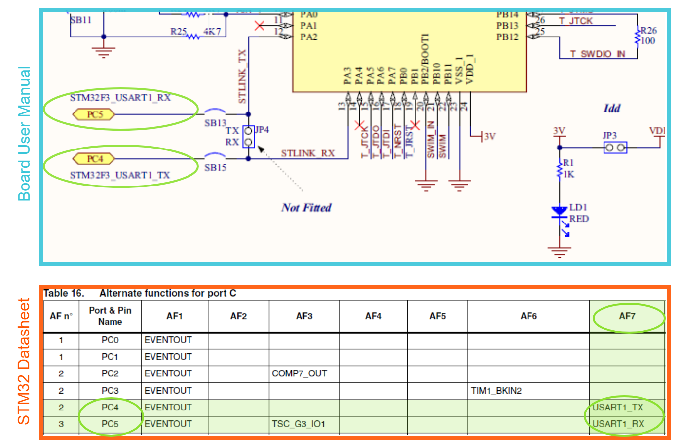
After some investigations, it will sort out that STLink VCP is physically connected to the STM32F3 UART1 through the GPIOs PC4 and PC5. Such information is available on the STM32F3 Discovery board user manual. The alternate function table to check how to reroute USART1_TX and USART1_RX on PC4 and PC5 is available on the STM32F303VC Datasheet.
Well, it will sort out that configuring the working mode of PC4 and PC5 as Alternate Function 7, the USART1 RX/TX lines will be re-routed on them.
For our discovery kit, such kind of initialization is already performed at board level (it would be better you had read GPIO/PAL article). Indeed, the following code box is an excerpt of the board file of the STM32F3 Discovery: we can notice that PC4 and PC5 have been labelled as LINE_VCP_RX and LINE_VCP_TX and that they have been configured as AF7
 * IO pins assignments.
 */
...

#define GPIOC_VCP_RX                4U
#define GPIOC_VCP_TX                5U

...

/*
 * IO lines assignments.
 */

...

#define LINE_VCP_RX                 PAL_LINE(GPIOC, 4U)
#define LINE_VCP_TX                 PAL_LINE(GPIOC, 5U)

...

/*
 * GPIOC setup:
 *
 * ...
 *
 * PC4  - VCP_RX                    (alternate 7).
 * PC5  - VCP_TX                    (alternate 7).
 *
 * ...
 */
For the sake of the knowledge, let us assume for this example that board files are not initializing these GPIOs correctly. In such case, we can put a remedy to this changing the board file or using the following code snippet after the halInit()
  palSetPadMode(GPIOC, 4U, PAL_MODE_ALTERNATE(7) | PAL_STM32_OSPEED_HIGHEST |
                           PAL_STM32_OTYPE_PUSHPULL);
  palSetPadMode(GPIOC, 5U, PAL_MODE_ALTERNATE(7) | PAL_STM32_OSPEED_HIGHEST |
                           PAL_STM32_OTYPE_PUSHPULL);
This snippet, executed once after the halInit() would overwrite the GPIO configuration. Note that to modify the board files is not suggested as they are shared between every project based on that development kit. Before to act on them we should create our own copy placing it inside our project folder editing the makefile to use these instead of the shared one. For now, let’s keep things simpler and let’s use the code snippet inside our main.
Serial driver enabling and peripheral allocation
I would assume that you already read the article about USART peripheral/Serial driver. This article shows that to use the Serial Driver you have to enable it in halconf.h setting the HAL_USE_SERIAL switch as TRUE and you have to allocate a peripheral to it in mcuconf.h. In this case, we would use the USART1 thus we will allocate it to the serial driver
/*
 * SERIAL driver system settings.
 */
#define STM32_SERIAL_USE_USART1             TRUE
Note that if we have started from the default STM32F3 Discovery demo, these switches would be already in the right position as default demo uses STLink VCP to print the test suite results.
Serial driver start and configuration
Every driver except PAL shall be configured before to be used. Even the serial driver shall be properly initialized and configured. This operation is carried out by the sdStart() function. I anyway as a quick recap:
- The sdStart() function receives two parameters: a pointer to the driver and a pointer to a configuration structure.
- There are multiple instances of the Serial Driver, one for each available USART, but each instance becomes available only when a peripheral is assigned to the driver
- The instance associated to USART1 is SD1
- The configuration structure of a driver could change from subfamily to subfamily. Up to now, this is not true for Serial Driver configuration which is the same across all the STM32 subfamilies
- The configuration structure is composed of 4 fields: speed, cr1, cr2 and cr3. The speed parameter is a 32-bit unsigned integer representing the baud rate of our serial driver, the other three are the initialization values of the control registers 1, 2 and 3 of our USART and are 16-bit unsigned integers.
- For the description of UART control registers, we should relay on the STM32F3 reference manual. For a more detailed explanation about how to deal with configuration structure, I suggest you read the paragraph “Configuring Serial Driver” of the article about Serial driver.
For our task, we basically need a configuration structure that looks like
static const SerialConfig myserialcfg = {
  115200,
  0,
  USART_CR2_STOP1_BITS,
  0
};
and the start call would look like
sdStart(&SD1, &myserialcfg);
Writing using the serial driver
The last but not the least piece of code we need to use is that which writes the string. The function we are going to use is the sdWrite which receives a pointer to the driver, a buffer of 8-bit unsigned integers and the size of this buffer.
With a slight deviation from the original task, I gonna write “Hello PLAY embedded” plus I will add some escape character (i.e. “\r\n”). Thus the whole string size is 22 and the code would look like
sdWrite(&SD1, (uint8_t*)"Hello PLAY embedded\r\n", 22U);
Note that the explicit cast, in this case, is required to avoid a warning at compile time.
Connecting the dots: the solution
Now we have all the pieces to compose the puzzle. Even if the task requires a single thread application, I would add a second thread that blinks a LED: it will act as a cheap and quick monitor to check whereas the application is running or not. The following code box is how the main.c file will be after our edits
#include "ch.h"
#include "hal.h"

/* Serial configuration. */
static const SerialConfig myserialcfg = {
  115200,
  0,
  USART_CR2_STOP1_BITS,
  0
};

/* Dummy LED blinker thread. */
static THD_WORKING_AREA(waThdBlinker, 128);
static THD_FUNCTION(ThdBlinker, arg) {

  (void) arg;
  chRegSetThreadName("Blinker");

  while(true) {
    palToggleLine(LINE_LED3_RED);
    chThdSleepMilliseconds(500);
  }
}

/* Application entry point. */
int main(void) {

  /* ChibiOS/HAL and ChibiOS/RT initialization. */
  halInit();
  chSysInit();

  /* Creating a dummy blinker thread. */
  chThdCreateStatic(waThdBlinker, sizeof(waThdBlinker), NORMALPRIO, ThdBlinker,
                    NULL);


  /* Enabling event on falling edge of PA0 signal.*/
  palEnablePadEvent(GPIOA, 0U, PAL_EVENT_MODE_FALLING_EDGE);

  /* Configuring VCP related GPIO. This configuration is already
     performed at board level initialization but is here reported
     only as example of how to configure GPIO at application level. */
  palSetPadMode(GPIOC, 4U, PAL_MODE_ALTERNATE(7) | PAL_STM32_OSPEED_HIGHEST |
                           PAL_STM32_OTYPE_PUSHPULL);
  palSetPadMode(GPIOC, 5U, PAL_MODE_ALTERNATE(7) | PAL_STM32_OSPEED_HIGHEST |
                           PAL_STM32_OTYPE_PUSHPULL);

  /* Starting Serial Driver 1 with our configuration. */
  sdStart(&SD1, &myserialcfg);

  /* main() thread loop. */
  while (true) {
    /* Waiting for a falling edge.*/
    palWaitPadTimeout(GPIOA, 0U, TIME_INFINITE);

    /* Printing a string over USART1 using Serial driver.*/
    sdWrite(&SD1, (uint8_t*)"Hello PLAY embedded\r\n", 22U);
  }
}
Connecting the dots one again: same project different board
What if we decide to use STM32 Nucleo-64 F401RE instead of STM32F3 Discovery? Well, the main difference is that on Nucleo board the VCP is connected to the STM32 through UART2 (PA2 and PA3) instead of USART1. This means we have to consider few differences related to the board layout:
- On the Nucleo-64 boards, VCP is connected to UART2 instead of USART1.
- LEDs and button are connected to different GPIOs.
This leads to some changes in our code:
- In muconf.h, we have to assign USART2 to the Serial Driver instead of USART1
- In serial related function calls, we have to use SD2 instead of SD1
- In main, we have to configure PA2 and PA3 instead of PC4 and PC5 (alternate functions could be different).
- In blinker thread, we have to blink a different line (LINE_LED_GREEN instead of LINE_LED3_RED).
- In PAL event/wait shall be configured on PC13 instead of PA0
The following code box is how the main.c file will be we are using an STM32 Nucleo-64
#include "ch.h"
#include "hal.h"

/* Serial configuration. */
static const SerialConfig myserialcfg = {
  115200,
  0,
  USART_CR2_STOP1_BITS,
  0
};

/* Dummy LED blinker thread. */
static THD_WORKING_AREA(waThdBlinker, 128);
static THD_FUNCTION(ThdBlinker, arg) {

  (void) arg;
  chRegSetThreadName("Blinker");

  while(true) {
    palToggleLine(LINE_LED_GREEN);
    chThdSleepMilliseconds(500);
  }
}

/* Application entry point. */
int main(void) {

  /* ChibiOS/HAL and ChibiOS/RT initialization. */
  halInit();
  chSysInit();

  /* Creating a dummy blinker thread. */
  chThdCreateStatic(waThdBlinker, sizeof(waThdBlinker), NORMALPRIO, ThdBlinker,
                    NULL);

  /* Enabling event on falling edge of PC13 signal.*/
  palEnablePadEvent(GPIOC, 13U, PAL_EVENT_MODE_FALLING_EDGE);

  /* Configuring VCP related GPIO. This configuration is already
     performed at board level initialization but is here reported
     only as example of how to configure GPIO at application level. */
  palSetPadMode(GPIOA, 2U, PAL_MODE_ALTERNATE(7) | PAL_STM32_OSPEED_HIGHEST |
                           PAL_STM32_OTYPE_PUSHPULL);
  palSetPadMode(GPIOA, 3U, PAL_MODE_ALTERNATE(7) | PAL_STM32_OSPEED_HIGHEST |
                           PAL_STM32_OTYPE_PUSHPULL);

  /* Starting Serial Driver 2 with our configuration. */
  sdStart(&SD2, &myserialcfg);

  /* main() thread loop. */
  while (true) {
    /* Waiting for a falling edge.*/
    palWaitPadTimeout(GPIOC, 13U, TIME_INFINITE);

    /* Printing a string over USART1 using Serial driver.*/
    sdWrite(&SD2, (uint8_t*)"Hello PLAY embedded\r\n", 22U);
  }
}
Interacting with the STM32
Create a project that is able to manage a LED getting a character from the terminal.
‘0’ -> turn off the LED
‘1’ -> turn on the LED
‘2’ -> blinks the LED
Let’s do this using again an STM32F3 Discovery. The goal is to get a character from the terminal and consequently take an action. To make things a little bit more challenging we are going to split our problem into two separate parts associating a thread to each one:
- getting the information from the Serial Driver
- taking an action
This approach aims to create two independent blocks which are able to communicate with each other. This offers a tremendous advantage: even if a block changes completely things will continue to work smoothly if the communication mechanism does not change. Do not worry if this is not completely clear know: it will be by the end of this example.
Getting an input
One of the parts of this problem is to get a character from a terminal and this can be easily done. Let us assume that this part would be performed by a thread that manages everything is related to the USART: this thread would be a well-defined entity that works independently. Thus, in here we have to configure everything is related to the USART plus we have to perform our reading operation.
/* Static variable which can be seen from every function of this module. */
static int8_t state = 0;

/* Serial configuration. */
static const SerialConfig myserialcfg = {
  115200,
  0,
  USART_CR2_STOP1_BITS,
  0
};

/* Sedial Driver thread. */
static THD_WORKING_AREA(waThdSerial, 256);
static THD_FUNCTION(ThdSerial, arg) {

  (void) arg;
  chRegSetThreadName("Serial manager");

  /* Configuring VCP related GPIO. This configuration is already
     performed at board level initialization but is here reported
     only as example of how to configure GPIO at application level. */
  palSetPadMode(GPIOC, 4U, PAL_MODE_ALTERNATE(7) | PAL_STM32_OSPEED_HIGHEST |
                           PAL_STM32_OTYPE_PUSHPULL);
  palSetPadMode(GPIOC, 5U, PAL_MODE_ALTERNATE(7) | PAL_STM32_OSPEED_HIGHEST |
                           PAL_STM32_OTYPE_PUSHPULL);

  /* Starting Serial Driver 1 with our configuration. */
  sdStart(&SD1, &myserialcfg);

  while(true) {
    /* Getting data from Serial Driver with a timeout. */
    int8_t tkn = sdGetTimeout(&SD1, TIME_MS2I(100));

    /* Checking if a timeout has occurred. */
    if(tkn != MSG_TIMEOUT) {
      /* Not a timeout. Echoing the character to improve user experience. */
      sdPut(&SD1, tkn);
      sdWrite(&SD1, (uint8_t*)"\r\n", 2U);

      if((tkn >= '0') && (tkn <= '2')) {
        /* Allowed character: updating state. Critical zone as the variable is shared.*/
        chSysLock();
        state = tkn;
        chSysUnlock();
      }
    }
    /* No sleep needed here. This thread releases the CPU on sdGetTimeout. */
  }
}
There is nothing new in the code outside the loop. Let’s thus concentrate on the loop of the thread. Basically, this code tries to get a character from the serial driver with a timeout. If it has effectively received a character it echoes and if the character is one of those actually allowed it updates a variable with the new value.
There are few things to point up about this code. Let’s start from the most important: the concurrent access to the variable state. This variable is declared with the static keyword. This means that is allocated statically in memory and this basically means that such a variable is placed at a specific memory address and never moved. It will be there for a lifetime (i.e. for the whole execution time). This variable is even global as it is declared outside any function and this means it can be seen from all the functions in this sheet. As threads are effectively functions, such a variable can be accessed from every thread declared in main.c. Considering this specific case we are planning to use this variable from two separate threads and this is what is called concurrent access. If not properly regulated, concurrent access can lead to variable value corruption. To avoid this we have placed the variable update in a Critical Zone: all the operation in this zone are atomic i.e. these operations cannot be interrupted for example by a context switch.
Another interesting note is about the thread timing: the function sdGetTimeout() is blocking and will internally put the calling thread in a sleep state until it does not receives a character or a timeout occurs: this means that no sleep is needed in this thread because context switch in favour of lower priority threads is guaranteed by this function.
To conclude, let’s take a look to the returning value of sdGetTimeout(): it could return MSG_TIMEOUT in case of operation timeout and this requires an additional check to ensure that we have actually received a character before to do something.
Taking an action
We can use another thread, like the main, to take an action. This thread has simply to access periodically the state variable and change the status of the LED consequently.
/* Application entry point. */
int main(void) {

  uint8_t curr_state = 0U;
  /* Stuff unrelated to the LED management. */
  ...

  /* main() thread loop. */
  while (true) {
    /* Updating the current state in a critical zone. */
    chSysLock();
    curr_state = state;
    chSysUnlock();

    /* Taking an action. */
    if(curr_state == '0') {
      /* Turning off the LED. */
      palClearLine(LINE_LED4_BLUE);
    }
    else if (curr_state == '1') {
      /* Turning on the LED. */
      palSetLine(LINE_LED4_BLUE);
    }
    else if (curr_state == '2') {
      /* Toggling the LED. The loop would do the blink*/
      palToggleLine(LINE_LED4_BLUE);
    }
    chThdSleepMilliseconds(250);
  }
}
Note that a critical zone shall be as small as possible in term of execution time and in term of the number of instruction executed in it. Copying the value of the shared variable in a local variable before to use it we can reduce the extension of the critical zone.
The solution
Now we can put things together and, as we have up to 8 LEDs on this board, we can even add the dummy blinker thread as a monitor that application is running.
#include "ch.h"
#include "hal.h"

/* Static variable which can be seen from every function of this module. */
static uint8_t state = 0;

/* Serial configuration. */
static const SerialConfig myserialcfg = {
  115200,
  0,
  USART_CR2_STOP1_BITS,
  0
};

/* Sedial Driver thread. */
static THD_WORKING_AREA(waThdSerial, 256);
static THD_FUNCTION(ThdSerial, arg) {

  (void) arg;
  chRegSetThreadName("Serial manager");

  /* Configuring VCP related GPIO. This configuration is already
     performed at board level initialization but is here reported
     only as example of how to configure GPIO at application level. */
  palSetPadMode(GPIOC, 4U, PAL_MODE_ALTERNATE(7) | PAL_STM32_OSPEED_HIGHEST |
                           PAL_STM32_OTYPE_PUSHPULL);
  palSetPadMode(GPIOC, 5U, PAL_MODE_ALTERNATE(7) | PAL_STM32_OSPEED_HIGHEST |
                           PAL_STM32_OTYPE_PUSHPULL);

  /* Starting Serial Driver 1 with our configuration. */
  sdStart(&SD1, &myserialcfg);

  while(true) {
    /* Getting data from Serial Driver with a timeout. */
    uint8_t tkn = sdGetTimeout(&SD1, TIME_MS2I(100));

    /* Checking if a timeout has occurred. */
    if(tkn != MSG_TIMEOUT) {
      /* Not a timeout. Echoing the character to improve user experience. */
      sdPut(&SD1, tkn);
      sdWrite(&SD1, (uint8_t*)"\r\n", 2U);

      if((tkn >= '0') && (tkn <= '2')) {
        /* Allowed character: updating state. Critical zone as the variable is shared.*/
        chSysLock();
        state = tkn;
        chSysUnlock();
      }
    }
    /* No sleep needed here. This thread releases the CPU onsdGetTimeout. */
  }
}

/* Dummy LED blinker thread. */
static THD_WORKING_AREA(waThdBlinker, 128);
static THD_FUNCTION(ThdBlinker, arg) {

  (void) arg;
  chRegSetThreadName("Blinker");

  while(true) {
    palToggleLine(LINE_LED3_RED);
    chThdSleepMilliseconds(500);
  }
}

/* Application entry point. */
int main(void) {

  uint8_t curr_state = 0U;

  /* ChibiOS/HAL and ChibiOS/RT initialization. */
  halInit();
  chSysInit();

  /* Creating a dummy blinker thread. */
  chThdCreateStatic(waThdBlinker, sizeof(waThdBlinker), NORMALPRIO, ThdBlinker,
                    NULL);

  /* Creating thew serial manager thread. */
  chThdCreateStatic(waThdSerial, sizeof(waThdSerial), NORMALPRIO, ThdSerial,
                    NULL);

  /* main() thread loop. */
  while (true) {
    /* Updating the current state in a critical zone. */
    chSysLock();
    curr_state = state;
    chSysUnlock();

    /* Taking an action. */
    if(curr_state == '0') {
      /* Turning off the LED. */
      palClearLine(LINE_LED4_BLUE);
    }
    else if (curr_state == '1') {
      /* Turning on the LED. */
      palSetLine(LINE_LED4_BLUE);
    }
    else if (curr_state == '2') {
      /* Toggling the LED. The loop would do the blink. */
      palToggleLine(LINE_LED4_BLUE);
    }
    chThdSleepMilliseconds(250);
  }
}
We decided to use two threads to create two independent blocks which are able to communicate with each other as this would offer an advantage in code reuse. To point out better this point let us assume that instead of driving a LED we would use the information received from serial driver to change the speed of a DC motor whereas 0 means stopped, 1 half speed and 2 full speed. In such case we just need to act on the loop of our main instead of changing the whole application and the serial thread as well as blinker thread can be copied as are.
Printing formatted strings
Create a project that prints current system time over the STLink Virtual COM port on button press.
For this task, we are going to need the chprintf(). We already introduced the “streams” module here. The quick recap is: to print formatted strings we need chprintf, to use chprintf we have to include streams to our project, to do that we have to edit the include section of our makefile.
Editing the makefile to include chprintf
To do that we have to identify the include section opening our makefile. We would easily identify it because it begins with a comment which states
##############################################################################
# Project, sources and paths
#
In here there is also the variable CHIBIOS we have to edit every time we duplicate a default demo. Well, right below there are many include statement. Here we have to add one more to include the streams module
include $(CHIBIOS)/os/hal/lib/streams/streams.mk
and our makefile would look like this
##############################################################################
# Project, sources and paths
#

# Define project name here
PROJECT = ch

# Imported source files and paths
CHIBIOS = ../../chibios182

# Licensing files.
include $(CHIBIOS)/os/license/license.mk
# Startup files.
include $(CHIBIOS)/os/common/startup/ARMCMx/compilers/GCC/mk/startup_stm32f3xx.mk
# HAL-OSAL files (optional).
include $(CHIBIOS)/os/hal/hal.mk
include $(CHIBIOS)/os/hal/ports/STM32/STM32F3xx/platform.mk
include $(CHIBIOS)/os/hal/boards/ST_STM32F3_DISCOVERY/board.mk
include $(CHIBIOS)/os/hal/osal/rt/osal.mk
# RTOS files (optional).
include $(CHIBIOS)/os/rt/rt.mk
include $(CHIBIOS)/os/common/ports/ARMCMx/compilers/GCC/mk/port_v7m.mk
# Other files (optional).
# include $(CHIBIOS)/test/lib/test.mk
# include $(CHIBIOS)/test/rt/rt_test.mk
# include $(CHIBIOS)/test/oslib/oslib_test.mk
include $(CHIBIOS)/os/hal/lib/streams/streams.mk
At this point, we can include the chprintf.h in the main file and use it.
The starting point
This problem is quite similar to the first exercise of this article. We can start from that solution to achieve our goal: we need to configure Serial Driver, we need the event/wait paradigm and eventually a dummy blinker thread. So our starting code would look like this
#include "ch.h"
#include "hal.h"

/* Serial configuration. */
static const SerialConfig myserialcfg = {
  115200,
  0,
  USART_CR2_STOP1_BITS,
  0
};

/* Dummy LED blinker thread. */
static THD_WORKING_AREA(waThdBlinker, 128);
static THD_FUNCTION(ThdBlinker, arg) {

  (void) arg;
  chRegSetThreadName("Blinker");

  while(true) {
    palToggleLine(LINE_LED3_RED);
    chThdSleepMilliseconds(500);
  }
}

/* Application entry point. */
int main(void) {

  /* ChibiOS/HAL and ChibiOS/RT initialization. */
  halInit();
  chSysInit();

  /* Creating a dummy blinker thread. */
  chThdCreateStatic(waThdBlinker, sizeof(waThdBlinker), NORMALPRIO, ThdBlinker,
                    NULL);

  /* Enabling event on falling edge of PA0 signal.*/
  palEnableLineEvent(LINE_BUTTON, PAL_EVENT_MODE_FALLING_EDGE);

  /* Starting Serial Driver 1 with our configuration. */
  sdStart(&SD1, &myserialcfg);

  /* main() thread loop. */
  while (true) {
    /* Waiting for a falling edge.*/
    palWaitLineTimeout(LINE_BUTTON, TIME_INFINITE);

    /* Magic here. */
  }
}
Note that here we have performed few dummy edits:
- We have removed VCP related GPIO configuration because this initialization is actually performed in board files. We added that code just to provide a practical example about what to do in case we need to change the GPIO configuration at the application level.
- In the event\wait APIs, we have used line instead of port and pad. Note that the identifier LINE_BUTTON is declared as usual in the board.h file as
/*
 * IO lines assignments.
 */
#define LINE_BUTTON                 PAL_LINE(GPIOA, 0U)
...
Now we need to add some specific code:
- we have to include the chprintf.h, nothing easier of that.
- we will get the current system time, and for this, we are going to use an API we have already used in the push-button long press/short press exercise: the chVTGetSystemTimeX() which return the current system time as system tick. We would even need of a macro to convert the value from system ticks to milliseconds.
- we will print a formatted string through the chprintf over the Serial Driver. We have already seen here that the chprintf() is identical to a C standard printf() but requires an additional parameter representing the stream on which it would write. It expects a pointer to BaseSequentialStream but actually, SerialDriver implements this interface thus we have everything we need to complete this task.
Let’s take a look at the solution which would clarify the previous statements
#include "ch.h"
#include "hal.h"

/* Including the chprintf. Remember that this requires the inclusion of
   streams.mk in the makefile. */
#include "chprintf.h"

/* Serial configuration. */
static const SerialConfig myserialcfg = {
  115200,
  0,
  USART_CR2_STOP1_BITS,
  0
};

/* This pointer to a sequential stream actually points to our serial driver.
   To use the serial driver in chprintf we need to cast it and we are using
   this variable to perform a cast only once. */
static BaseSequentialStream* chp = (BaseSequentialStream*) &SD1;

/* This would store the current systime. */
static systime_t now;

/* Dummy LED blinker thread. */
static THD_WORKING_AREA(waThdBlinker, 128);
static THD_FUNCTION(ThdBlinker, arg) {

  (void) arg;
  chRegSetThreadName("Blinker");

  while(true) {
    palToggleLine(LINE_LED3_RED);
    chThdSleepMilliseconds(500);
  }
}

/* Application entry point. */
int main(void) {

  /* ChibiOS/HAL and ChibiOS/RT initialization. */
  halInit();
  chSysInit();

  /* Creating a dummy blinker thread. */
  chThdCreateStatic(waThdBlinker, sizeof(waThdBlinker), NORMALPRIO, ThdBlinker,
                    NULL);

  /* Enabling event on falling edge of PA0 signal.*/
  palEnableLineEvent(LINE_BUTTON, PAL_EVENT_MODE_FALLING_EDGE);

  /* Configuring VCP related GPIO. This configuration is already
     performed at board level initialization but is here reported
     only as example of how to configure GPIO at application level. */
  palSetPadMode(GPIOC, 4U, PAL_MODE_ALTERNATE(7) | PAL_STM32_OSPEED_HIGHEST |
                           PAL_STM32_OTYPE_PUSHPULL);
  palSetPadMode(GPIOC, 5U, PAL_MODE_ALTERNATE(7) | PAL_STM32_OSPEED_HIGHEST |
                           PAL_STM32_OTYPE_PUSHPULL);

  /* Starting Serial Driver 1 with our configuration. */
  sdStart(&SD1, &myserialcfg);

  /* main() thread loop. */
  while (true) {
    /* Waiting for a falling edge.*/
    palWaitLineTimeout(LINE_BUTTON, TIME_INFINITE);

    /* Updating now. */
    now = chVTGetSystemTimeX();

    /* Printing now on the terminal. */
    chprintf(chp, "Current systime is %d ms\r\n", TIME_I2MS(now));
  }
}
Hi,
using this code
uint32_t command;
float intensity;

while (true)
{
  /*
   * Linear ADC conversion.
   */
  adcConvert(&ADCD1, &adcConfig, adcSamples, ADC_GRP1_BUF_DEPTH);

  chprintf(DebugPort_UART2, "ADC: %d %d %d %d\n", adcSamples[0],adcSamples[1],adcSamples[2],adcSamples[3]);

  chprintf(DebugPort_UART2, "Int: %d CMD: %x\n",(int)(intensity*10), command);

  chThdSleepMilliseconds(200);
}
reliably crashes an F042 chip. When I comment out either chprintf line, all is good. Tried to increase serial buffers, but no help. Anything I am doing wrong?
Thanks
Ciao,
enable debug options in chprintf and check whereas the operating system detects an anomaly and stops in a controlled way.
to me, it sounds like a buffer overflow. Check the adcSamples size.
Hi Rocco,
thanks for the response. The issue was solved by switching back to gcc 5.xx as suggested by chibios 19 for an M0 core. Solved a lot of other issues as well. It might be worthwhile to warn users even more clearly that newer gcc does not work with these chips.
Cheers,
Kai
Great site by the way. Finally got me going with CHIBIOS. Looking forward to the next articles.
Thanks for commenting… I have never noticed this problem because I tend to use the latest version of ChibiStudio and in the latest version we have GCC 5.4 and 7.0. I suppose your comment would be helpful to many readers.
Hi Rooco,
No matter what I tried, I could not manage the work for it stm32f407vg-disc1 board. Basically I am using the code of “Connecting the dots one again: same project different board” section which must be identical when it comes to USART2.
Do you have any example serial communication sketch for my board? Thank you.
By the way I appreciate the work you guys have done. It is fantastic. Keep up the good work.
Cheers,
Eren
Hey there,
I am not 100% sure but the f407 discovery lacks the connection between a STM32 usart and the STLink VCP. Maybe you need to bridge them with duponts. This info is on the user manual of your board.
There is one piece of information that I am still looking for after reading that helpful article. When connected via STLink to ChibiStudio and writing to the associated serialDriver, where can I see the output of the print statements run by the test suite (I am running the F401RE demo)? Should they be in the OpenOCD console? I typically only see:
Info : halted: PC: 0x0800e006
Info : halted: PC: 0x080062e0
Info : Previous state query failed, trying to reconnect
Polling target stm32f4x.cpu failed, trying to reexamine
Info : stm32f4x.cpu: hardware has 6 breakpoints, 4 watchpoints
Hello Guillaume,
when you print on the Serial connected to the STLink you will see the output in a terminal. You can either use the Terminal of Eclipse or an external terminal (such as Putty, RealTerm). Connect to the STLink Virtual COM port (check the number in the Device Manager), 8-bit, no parity, no flow control 38400bps. If you are using the default demo just press the button (blue) and you will see the output of the ChibiOS test suit.
Ciao Rocco, using putty worked nicely! I would recommend to mention those steps somewhere in the article as it’s a very natural thing to do when looking for the output of those print statements. Thanks for the prompt answer.
I will Guillaume,
thanks for the feedback.
Hi!
How can I mitigate the bounce effect at the ChibiOS level when I use “palWaitLineTimeout(LINE_BUTTON, TIME_INFINITE);” from your example?
Does it have any “confirmation time” functionality?